|
| |
TM 5-4210-233-14&P-1
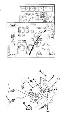
4-36. RELIEF VALVE PILOT ASSEMBLY
This task covers:
a.
Removal
c.
Follow-on Maintenance
b.
Installation
TOOLS REQUIRED
EQUIPMENT CONDITION
Tool Kit, General Mechanics, Automotive
Main Engine Shutdown (see para 2-12 .)
(Appendix B, Section III, Item 1)
APU Shutdown (see para 2-16 .)
Batteries Disconnected (see para 4-114 .)
MATERIALS/PARTS REQUIRED
Gauge Panel Removed (see para 4-18 .)
Pipe Sealing Compound (Item 2, Appendix E)
a.
Removal.
(1)
Tag and disconnect three hoses (1, 2 and 3).
(2)
Remove pins (6 and 7) and remove valve
handles (8 and 9).
(3)
Unscrew knob (1 0) and remove strainer.
(4)
Remove two screws (11), nuts (12) and
lockwashers (13). Remove pilot assembly (14).
(5)
If necessary, remove drain cock (15) from pilot
assembly (14).
b.
Installation.
NOTE
Coat all threads with pipe sealing compound
(Item 2, Appendix E).
(1)
If necessary, install drain cock (15) in pilot
assembly (14).
(2)
Put pilot assembly (14) in position on pump
panel and secure with two screws (11),
lockwashers (13) and nuts (12).
(3)
Install strainer (10) in pilot assembly (14).
(4)
Install valve handles (8 and 9) and install pins (6
and 7).
(5)
Connect hoses (1, 2 and 3) to pilot assembly
(14).
4-204
|

