|
| |
TM 5-4210-233-14&P-1
4-35. RELIEF VALVE
This task covers:
a.
Removal
c.
Follow-on Maintenance
b.
Installation
TOOLS REQUIRED
EQUIPMENT CONDITION
Tool Kit, General Mechanics, Automotive
Piping Drained (see para 2-17 .)
(Appendix B, Section III, Item 1)
Main Engine Shutdown (see para 2-12 .)
APU Shutdown (see para 2-16 .)
MATERIALS/PARTS REQUIRED
Batteries Disconnected (see para 4-114 .)
O-rings (Fig 36, Appendix F)
Curbside Pump Panel Removed (see para 4-26 .)
a.
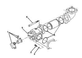
Removal.
(1)
Disconnect wires and remove micro switch
and bracket (1).
(2)
Remove four bolts (2) and four washers (3).
(3)
Remove two bolts (4).
(4)
Remove relief valve (5) and pipe (7).
(5)
Remove and discard three O-rings (6).
b.
Installation.
(1)
Install three new O-rings (6).
(2)
Install pipe (7) and relief valve (5); secure
relief valve (5) with two bolts (4), four bolts (2)
and four washers (3).
(3)
Install micro switch and bracket (1) and
reconnect wires.
c.
Follow-on Maintenance.
(1)
Install curbside panel (see para 4-26).
(2)
Connect batteries (see para 4-114).
(3)
Test relief valve operation (see para 2-13).
4-203
|