|
| |
TM 5-4210-233-14&P-1
1-10. LOCATION AND DESCRIPTION OF MAJOR COMPONENTS - Continued
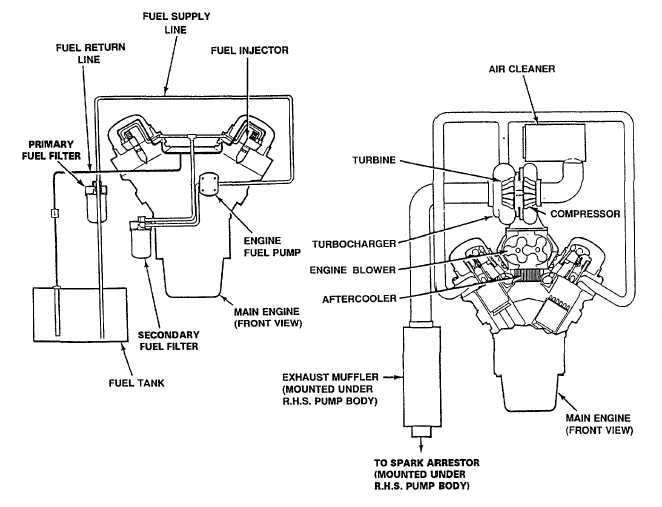
Figure 1-5. Fuel, Air Intake and Exhaust Systems
e. Electrical System.
(1) Refer to Electrical Schematics in Appendix H. The fire truck is equipped with a 12 VDC main electrical
system and a 110 VAC auxiliary system. All components and subsystems used to operate and control
the truck and firefighting equipment are powered from the 12 VDC system. The 110 VAC system is
used to operate auxiliary power tools, lights, and accessories.
(2) The 110 VAC system is powered by the auxiliary power unit (APU) The truck is equipped with five 110
VAC outlets. There are two double receptacles on each side of the hose body and one single receptacle
at the ladder tip.
(3) The 12 VDC system is equipped with two 12-volt batteries. Each battery is located in a separate battery
compartment. The batteries are connected to a four-position battery switch in the cab. The batteries
charge is maintained by one 160-amp engine-driven alternator. All major components and circuits are
protected by automatic reset circuit breakers.
1-8
|