|
| |
TM 5-4210-233-14&P-1
1-10. LOCATION AND DESCRIPTION OF MAJOR COMPONENTS - Continued
c. Engine.
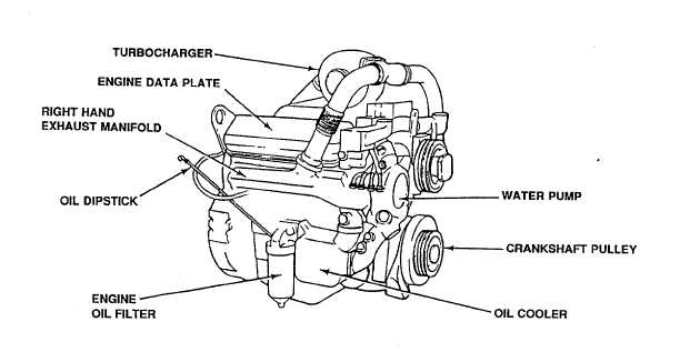
(1) The truck is equipped with a turbocharged, V-configuration, eight-cylinder, water-cooled, two-cycle
diesel engine. The engine develops 450 horsepower (336 kw) at a governed speed of 2100 rpm.
(2) Access to the engine oil dipstick can be gained through an access door located inside the curbside
passenger compartment of the cab.
Figure 1-4. Truck Engine
d. Fuel, Air Intake, and Exhaust Systems.
(1) The fuel system includes: a sixty-five gallon (246 1) fuel tank, engine fuel pump, primary and secondary
fuel filters, and supply and return lines between fuel tank and engine.
(2) The air intake system includes: the air filter, turbocharger compressor, and engine blower. The air filter
is mounted above the engine and connected to the turbocharger.
(3) The exhaust system includes: exhaust piping, turbocharger turbine, muffler, and spark arrester. The
exhaust pipe is mounted to the turbocharger. The spark arrestor and the muffler are mounted to the
frame with hanger brackets.
1-7
|