|
| |
TM 5-4210-233-14&P-1
5-76. APU ENGINE OIL PUMP AND OIL BASE - Continued
b.
Disassembly.
(1)
Remove the switch cover (10), revealing the
point set.
(2)
Remove the point set assembly (9) by
removing the screws holding it to the plate
(7). Pull out the plunger (6) and plunger
diaphragm (8).
(3)
Remove
the
centrifugal
switch
plate,
revealing the cam and weight assembly.
(4)
Pull out the cam and weight assembly.
c.
Cleaning and Inspection.
(1)
Thoroughly clean the gear (4) and cam (11) assembly, the bearing surfaces in the gear case and
breaker plate, and oil trickle holes to these bearings. Check the oil spray hole in the gear case to
be sure it is open.
(2)
Check for wear in the spacer, fibre plunger and the spring loaded shaft plunger. The spacer must
be at least .35 in. (8.9 mm) long. If not, replace it immediately. Push the weights outward; they
should move freely. If they don't or if any part of the assembly is sticking or worn, replace the cam
and weight assembly. If the cam is loose on the gear shaft, replace the assembly.
(3)
If the breaker gap cannot be maintained at .040 in. (1.02 mm), check the fibre plunger and spacer
for wear.
d.
Assembly.
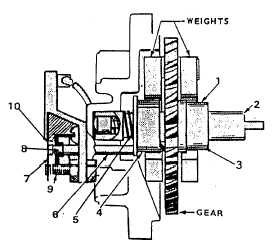
(1)
Install the spacer (1) on the shaft (2) and install the shaft assembly into the gear case (3). Match it
with the cam gear (4).
(2)
Install the spring (5) and plunger (6) into the end of the shaft (2).
(3)
Install the breaker plate (7).
(4)
Install the plunger (6) and diaphragm (8).
(5)
install the breaker points (9) on the breaker plate (7) and set the gap at .040 in. (1.02 mm).
(6)
Install the switch cover (10).
5-398
|