|
| |
TM 5-4210-233-14&P-1
5-74. APU PISTONS, RINGS AND CONNECTING RODS - Continued
(7)
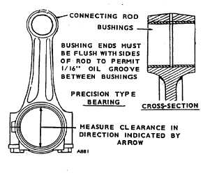
Clean the connecting rod and check for
defects. Check the connecting rod bushing
for proper clearance with the piston pin.
Clearance should be .0002 in. to .0007 in.
(.0051 to .0178 mm).
(8)
If the bushings are excessively worn, press
them out and press one new bushing in from
each side of the bushing bore. Press the new
bushings only until flush with the sides of the
rod to leave 1/16 in. to 7/64 in. (1.6 to 2.8
mm) oil groove in the center.
(9)
Inspect the connecting rod bearings for burrs,
breaks, pits and wear. Measure the clearance
between bearings and the crankshaft journal.
The clearance should be .001 in. to .0033 in.
(.0254 to .0838 mm). If necessary, place with
new standard or oversize precision bearings.
c.
Installation.
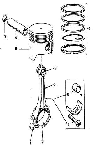
(1)
Install the connecting rod (2) in the piston (5)
with the pin (4) and retaining rings (3). If new
bushings (8) were installed, make certain the
ends are flush with the connecting rod to
provide for the oil recess in the center.
(2)
Using a ring expander, install the rings (6) on
the piston (5). Rings (6) will be marked top,
or identified in some other manner. Place
this mark toward the closed end of the piston
(5). Space the ring gaps one fourth of the way
around the piston from one another. No gap
should be in line with the piston pin. Oil (Item
10, Appendix E) the rings and piston. Gap in
oil ring expander must be approximately 1800
from gap in oil ring.
(3)
Position a bearing half (7) in the connecting
rod (2). Be sure there is not dirt under the
bearing. This could cause high spots and
early bearing failure.
(4)
Oil the cylinder wall. Install the piston and rod
assembly in the cylinder, using a suitable
installer. The assembly should be installed
with the stamp on the piston facing in the
same direction as when removed. The notch
on the piston should be towards the front of
the engine.
5-393
|