 |
|||
|
|
|||
|
Page Title:
Turbo Boost Air Pressure Sensor |
|
||
| ||||||||||
|
|
 TM 5-4210-233-14&P-1
5-28. DDEC ELECTRONIC CONTROL MODULE AND SENSORS - Continued
(3)
Installation.
(a) Install bracket (14) in position on engine and secure with two screws (15) and lockwashers (5).
Install screws (3, 16 and 17), three lockwashers (2) and three flat washers (1).
(b) Install plate (10) and shield (12) on control module (13) and secure with eight screws (11).
(c) Install fitting block (7) on end of plate (10). Install new seals (8) and secure fitting block to plate
with two screws (9).
(d) Install eight isolator mounts (4) on control module (13) and install module in position on bracket
(14) and secure with four screws (6) and lockwashers (5).
(e) Connect two fuel hoses to fitting block (7).
(f) Refer to a. above and connect wiring harnesses to control module.
c.
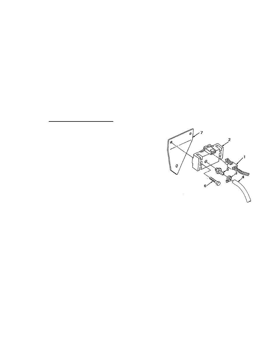
Turbo Boost Air Pressure Sensor
.
(1) Removal.
(a) Disconnect wiring harness (1) from
air pressure sensor (2).
(b) Loosen clamp (3) and disconnect
hose (4) from hose fitting (5).
(c) Remove two screws (6) and lift
turbo boost pressure sensor (2)
from bracket (7).
(2)
Cleaning and Inspection.
(a) Wipe sensor and hose clean with a
dry, clean, lint free cloth (Item 42,
Appendix E).
(b) Inspect hose for cracks, damage
and evidence of leakage.
(c) Inspect hose fitting for damaged
threads.
(d) Replace any damaged components.
5-186
|
|
Privacy Statement - Press Release - Copyright Information. - Contact Us |
