 |
|||
|
|
|||
|
Page Title:
AERIAL LADDER ANGLE LIMIT SWITCH |
|
||
| ||||||||||
|
|
 TM 5-4210-233-14&P-1
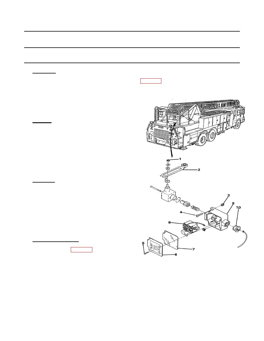
4-197. AERIAL LADDER ANGLE LIMIT SWITCH
THIS TASK COVERS:
a. Adjustment
c. Installation
b. Removal
d. Follow-on Maintenance
TOOLS REQUIRED
Tool Kit, General Mechanics, Automotive
(Appendix B, Section III, Item 1)
a. Adjustment.
(1) Raise ladder to approximately 65 deg. position (see para 2-14).
(2) Loosen nut (1).
(3) Move arm (2) so that it just touches base of ladder.
(4) Tighten nut (1).
b. Removal.
(1) Remove nuts (3) and screws (4).
(2) Remove screws (5), cover (6) and gasket (7).
(3) Tag and disconnect wires from switch (8).
(4) Remove switch (8) from switch housing (9).
(5) Remove wires and seal (10) from switch housing (9).
c.
Installation.
(1) Install seal (10) and wires in switch housing (9).
(2) Install switch (8) in switch housing (9).
(3) Attach wires to switch (8).
(4) Install gasket (7), cover (6) and screws (5).
(5) Attach switch housing (9) with screws (4) and nuts (3).
d. Follow-on Maintenance.
(1) Bed ladder (see para 2-14).
4-496
|
|
Privacy Statement - Press Release - Copyright Information. - Contact Us |