|
| |
TRUCK SERVICE MANUAL
TM 5-4210-230-14&P-1
INSTRUMENTS
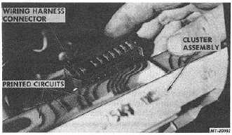
Fig. 3 Removing Wiring Harness Connector
4.
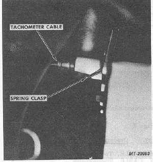
Press down on quick-connect spring clasp (Fig. 4) and
disconnect flexible cables from back of speedometer
and tachometer.
5.
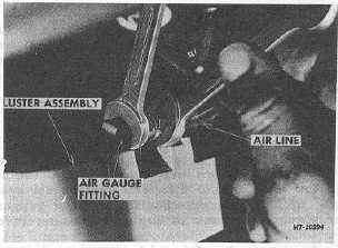
Unscrew air or vacuum lines from fittings (Fig. 5) on
back of air or vacuum gauges. Two gauges are used
with air braked trucks --one gauge only with vacuum
(hydraulic) braked trucks.
6.
Instrument cluster assembly is now free to be removed
from instrument panel.
Fig. 4 Releasing Speedometer and Tachometer Cable
Fig. 5 Removing Air or Vacuum Lines
Remove Instrument Cluster Components
If it is desired that individual components are to be
removed, procedure is as follows:
1.
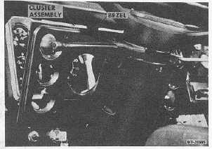
With the four cluster mounting screws removed,
remove a fifth mounting screw front center of cluster
bezel and detach bezel (Fig. 6).
Fig. 6 Removing Instrument Cluster Bezel
2.
Individual gauges can now be removed by loosening
gauge mounting screws as required. All electrically
actuated gauges (Fig. 7) are removed from front and
have plug-in spring loaded connections. Speedometer
and tachometer (Fig. 8) are also front serviceable and
can be removed from cluster without disconnecting
cables. (If cables are to be removed, these are quick-
disconnect from rear of cluster.)
CTS-2735 Page 4
PRINTED IN UNITED STATES OF AMERICA
|