|
| |
TRUCK SERVICE MANUAL
TM 5-4210-230-14&P-1
INSTRUMENTS
DESCRIPTION SYSTEM
Instruments used on S-Series trucks include voltmeter,
fuel gauge, oil pressure gauge, water temperature gauge,
speedometer, tachometer and air or vacuum gauges, plus oil,
water, brake and power divider lock warning lights.
All of the aforementioned instruments are located on the
instrument panel in a demountable instrument cluster (Fig. 1)
directly in front of the driver. Gauges and panel lights of the
cluster are connected to the vehicle electrical system by a
flexible printed circuit. Optional gauges for such other items as
engine oil temperature, transmission oil temperature, hour
meter, etc. are located to the right of heater controls in a
separate panel. Optional gauges are wired independent of the
printed circuit.
INSTRUMENT CLUSTER
The instrument cluster is a reliable, quick disconnect
package for the most commonly used
instruments. Should the need arise, cluster body can be quickly
detached from the instrument panel for quick access to any of
its components. Either the complete cluster assembly or its
components can be replaced.
CAUTION
Always disconnect battery negative (ground)
cable before servicing instrument cluster or its
components.
Remove Complete Cluster
1.
Unscrew the four cluster mounting screws.
2.
Tilt or lift out cluster assembly from instrument panel
(Fig. 2).
3.
Pull wiring harness connector from printed circuit on
back of cluster assembly (Fig. 3).
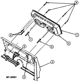
Fig. 2 Removing Instrument Cluster
Legend for Fig. 2
Key
Description
1
BEZEL, Instrument Cluster
2
CLUSTER, Assembly
3
PANEL, Instrument
4
NUT, Spring 8-18
5
CONNECTOR, Wiring Harness
Key
Description
6
CABLE, Tachometer
7
CABLE, Speedometer
8
HOSE, Air Pressure
9
SCREW, Mounting #8-18 x 2-1/4
CTS-2735 Page 3
PRINTED IN UNITED STATES OF AMERICA
|