|
| |
TRUCK SERVICE MANUAL
TM 5-4210-230-14&P-1
FUEL SYSTEM
9.
Clamp the pump in a vise having soft jaws. Pull the
cam lever to the full intake position and hold while
tightening the housing to the pump body mounting
screws. This will allow the diaphragm to position itself
properly.
10.
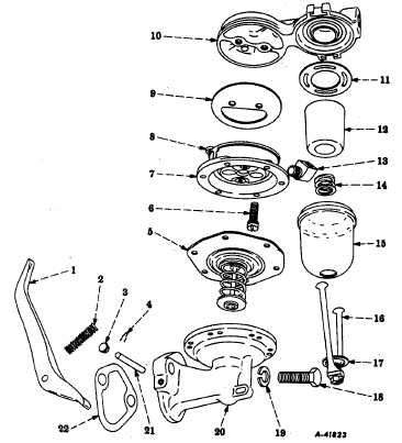
Place filter bowl gasket (11), new filter (12T, filter
spring (14) and filter bowl (15) over the cover section of
air dome and filter cover (10) and secure in place with
retainer (16).
Fig. 6 Exploded View of Side-Mounted Bowl Type Fuel Pump
Legend for Fig. 6
Key
Description
Key
Description
1
LEVER, Cam
12
FILTER, Glazed Ceramic or Paper
2
SPRING, Cam Lever Return
13
ELBOW
3
PLUG, Cam Lever Shaft Seal
14
SPRING, Filter
4
PIN, Spring, Cam Lever Shaft Retaining
15
BOWL, Filter
5
DIAPHRAGM, Assembly
16
RETAINER, with Screw Assembly
6
SCREW, with Lockwasher, Assembly
17
WASHER, Filter Bowl Retaining
7
HOUSING, Valve Assembly
18
BOLT, Hex Head
8
SCREW, with Lockwasher, Assembly
19
LOCKWASHER
9
DIAPHRAGM, Air Dome
20
PUMP BODY
10
AIR DOME and FILTER COVER
21
PIN, Cam Lever
11
GASKET, Filter Bowl
22
GASKET, Pump-to-Crankcase
Electric In-Tank Mounted Type
There is no service on the in-tank mounted electric fuel pump--only complete replacement of the pump itself. Do not
disassemble the electric fuel pump.
CTS-2050-F Page 8
PRINTED IN UNITE D STATES OF AMERICA
|