|
| |
TRUCK SERVICE MANUAL
TM 5-4210-230-14&P-1
FUEL SYSTEM
7.
Take out the two valve housing-to air dome and filter
cover mounting screws and separate the valve housing
from the air dome and filter cover. Remove the air
dome diaphragm.
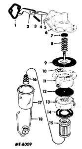
Fig. 5 Exploded View of Suspended Bowl Type Fuel Pump
Legend for Fig. 5.
Key
Description
1
GASKET, Mounting
2
LEVER, Cam
3
SPRING, Cam Lever
4
LEVER, Diaphragm
5
PIN, Cam Lever
6
BODY, Pump
7
SEAL, Oil Assembly
8
SPRING, Diaphragm
9
DIAPHRAGM, Pump
10
VALVE, Inlet and Outlet
11
HOUSING, Valve
12
DIAPHRAGM, Air Dome
13
COVER
14
GASKET, Element Bowl
15
ELEMENT, Paper or Ceramic
16
SPRING, Element (If Used)
17
BOWL, Fuel
18
RETAINER, with SCREW
Inspection
Whenever the fuel pump is serviced there are some
parts which should always be replaced whether the old parts
appear serviceable or not. These parts are the diaphragm
assembly, air dome diaphragm, filter bowl gasket, ceramic or
paper filters, valve and cage, cam lever shaft seal plug and
the pump-to-crankcase gasket. Fuel pump repair kits
containing all these parts are available. All other parts should
be inspected as follows:
1.
Inspect the pump body, valve housing, air dome and
filter cover for cracks or breakage in castings.
2.
Check the mating surfaces of castings for warpage.
3.
Inspect the body and cover for stripped screw threads.
4.
Check the rocker arm for wear at the camshaft contact
point and also at the pivot point.
Assembly
All suspended or side-mounted bowl type fuel pumps
will have an assembly procedure similar to the following.
Refer to Fig. 6.
1.
Place new air dome diaphragm (9) on the dome section
of air dome and filter cover (10). Position the open half
of the diaphragm over the inlet section of the air dome.
2.
Install the valve and cage assembly in the valve
housing if they were removed.
3.
Assemble valve housing assembly (7) to the air dome
and filter cover assembly so that the intake side of the
housing mates with the intake side of the air dome.
Insert two mounting screws (6) with lockwashers and
tighten securely.
4.
Install new diaphragm assembly (5) to pump body (20).
5.
Insert cam lever (1) into the opening in the pump body.
Compress the diaphragm spring slightly so that the
forked end of the cam lever engages under the retainer
on the end of the diaphragm spring.
6.
Fasten the cam lever in the pump body with cam lever
pin (21) and secure the pin with cam lever shaft
retaining spring pin (4). Seal the pin opening in the
pump body with cam lever shaft seal plug (3).
7.
Check the match marks made at the time of
disassembly on the pump body and valve housing
assembly and install the valve housing assembly to the
pump body.
8.
Install mounting screws (8) with lockwashers but
tighten only enough for the screws to just touch the
lockwashers.
CTS-2050-F Page 7
PRINTED IN UNITED STATES OF AMERICA
|

