|
| |
ENGINE DIVISION SERVICE MANUAL
TM 5-4210-230-14&P-1
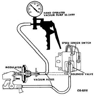
Fig. 61 Modulator Test
(5)
If modulator is improperly adjusted, loosen lock nut
and adjust position of modulator.
(6)
Repeat Steps (3) thru (5) until proper speed is
achieved; then tighten lock nut.
(7)
Reconnect proper vacuum hose to modulator.
c.
Perform DTM operational test as follows:
(1)
Verify modulator is retracted at idle.
(2)
Slowly accelerate the engine and observe the speed
at which the modulator extends. Modulator should
extend at 1850 + 50 RPM (Fig. 60).
(3)
Slowly decelerate the engine and observe the speed
at which the modulator retracts. Modulator should
retract at 1850 + 50 RPM (Fig. 60).
d.
Verify solenoid valve functions properly.
(1)
Operate engine at any condition.
(2)
With wiring harness disconnected from solenoid
valve, modulator must be in retracted position.
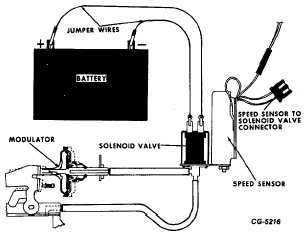
Fig. 62 Jumper Wires from Battery to Solenoid Valve
Terminals
(3)
With jumper wires from positive terminal of battery
and from ground connected to solenoid valve
terminals (Fig. 62), modulator must be in extended
position.
(4)
If modulator does not function properly, solenoid
valve is faulty and must be replaced. (The solenoid
valve and speed sensor are sold as one assembly.)
e.
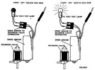
Verify speed sensor functions properly.
(1)
Disconnect wiring harness from solenoid valve and
connect a 12-volt test lamp between the two
terminals of the harness connector.
Fig. 63 Speed Sensor Switch Test
CGES-215 Page 36
PRINTED IN UNITED STATES OF AMERICA
|