|
| |
ENGINE DIVISION SERVICE MANUAL
TM 5-4210-230-14&P-1
b.
Be sure hoses are connected properly to low
temperature vacuum control valve.
c.
If hoses are satisfactory and vacuum does not pass
through low temperature vacuum control valve, valve
is faulty and must be replaced.
After correcting any problem and obtaining a vacuum
signal at EGR valve, repeat System Operation Test per c and
d above.
Check operation of EGR valve as follows:
a.
Remove EGR valve from engine.
b.
Visually inspect valve for evidence of valve pintle
(plunger) not seating. If pintle does not seat due to
deposits, clean valve pintle and seat (see EGR Valve
Cleaning Procedure). If pintle does not seat properly
after cleaning, replace EGR valve.
c.
Apply 10-12" Hg vacuum to EGR valve vacuum port
(Fig. 51). As vacuum is applied, valve pintle should
move off seat and retract into valve housing until end
of pintle is approximately flush with surface of valve
housing. If valve does not operate when vacuum is
applied, valve is faulty and should be replaced. 15A.
Replace EGR Valve
15A.
Replace EGR Valve
Because EGR valve metering varies between engines, it
is important that the correct EGR valve be used in order to
obtain optimum engine performance and emission control
(see EGR Valve Application Chart).
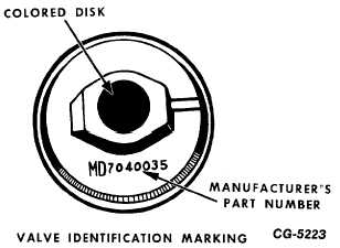
To assist in identification, EGR valves are coded by a
colored disk attached to the center of the vacuum diaphragm
housing. The valve may also be identified by the
manufacturer's part number stamped on the valve (Fig. 54).
15B.
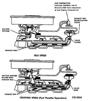
Exhaust Gas Recirculation System Operation.
The exhaust gas recirculation (EGR) system introduces a
metered amount of exhaust gas into the intake manifold
where it mixes with the air/fuel mixture entering the
combustion chambers. Dilution of the air/fuel mixture with
exhaust gas lowers combustion temperature and pressure,
thereby reducing formation of oxides of nitrogen.
Fig. 54 EGR Valve Identification Marking
Fig. 55 Exhaust Gas Recirculation System
(Single Diaphragm EGR Valve)
The EGR valve regulates the amount of exhaust gas
entering the intake manifold. The EGR valve is controlled by
ported vacuum, which is determined by position of the
carburetor throttle plate(s). Operation of the exhaust gas
circulation system is illustrated in Figures 55 and 56.
While the engine is stopped or operating at idle speed
(negligible port vacuum), the EGR valve is held closed by
spring pressure.
CGES-215 Page 30
PRINTED IN UNITED STATES OF AMERICA
|