|
| |
ENGINE DIVISION SERVICE MANUAL
TM 5-4210-230-14&P-1
If minimum speed drop specification is not achieved,
verify applied vacuum signal acts on valve.
a.
Tee vacuum gauge into vacuum hose at EGR valve
(upper port on dual diaphragm valves).
b.
With
engine
shut
off
and
normal
operating
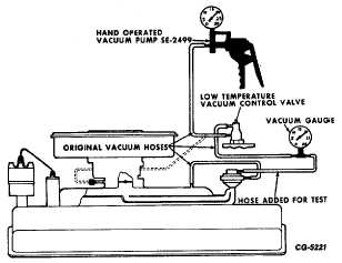
temperature (EGR low temperature vacuum control
valve), any vacuum magnitude applied at carburetor
end of vacuum hose should be observed at EGR
valve end of hose (Fig. 52).
c.
If same vacuum is not observed, inspect vacuum
hoses for leaks and replace as necessary.
d.
Repeat Step b. If same vacuum is not observed,
replace EGR low temperature vacuum control valve.
e.
Repeat EGR System Functional Test.
If minimum speed drop specification is still not achieved,
check for plugged exhaust gas passages and clean as
required.
Fig. 52 Low Temperature Vacuum Control Valve and
Connecting Hose Test
a.
Open carburetor throttle plates and examine exhaust
gas ports located in floor of intake manifold directly
below carburetor. If ports are plugged with deposits
remove carburetor and clean ports as needed.
For Canada V-304/345 Engines Only
a.
Operate engine until it reaches normal operating
temperature.
b.
Shut off engine. Connect tachometer and vacuum
gauge to engine.
c.
Start engine and block throttle open to give 3000
RPM. Observe and record tachometer reading.
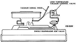
Fig. 53 Single Diaphragm EGR Valve System
d.
Disconnect EGR vacuum signal hose (Fig. 53) and
again record tachometer reading. If EGR system is
functioning properly the minimum speed increase
should be 50 rpm for the V-304 and 150 rpm for the
V-345. If rpm increase is less than shown above,
EGR system is not functioning properly and should
be checked per the following steps.
Check low temperature vacuum control valve as follows:
a.
With engine operating at fast idle, disconnect
vacuum signal hose from low temperature vacuum
control valve. A vacuum signal should be felt at the
open end of hose. If vacuum is felt, reconnect hose
and proceed. If vacuum is not felt, stop engine and
check for leaking or restricted vacuum hose or
restricted vacuum port in carburetor.
b.
With engine operating at fast idle, disconnect
vacuum signal hose from EGR valve. A vacuum
signal should be felt at the open end of the hose. If
vacuum is felt, vacuum supply and low temperature
valve are satisfactory (Fig. 53).
If vacuum is not felt:
a.
Check for leaking or restricted vacuum hose.
CGES-215 Page 29
PRINTED IN UNITED STATES OF AMERICA
|


