|
| |
ENGINE DIVISION SERVICE MANUAL
TM 5-4210-230-14&P-1
idle, cruise, acceleration, etc.). The valve itself consists of a
coil spring, valve and a two-piece outer body which is crimped
together. The valve dimensions, spring and internal
dimensions are such to produce the desired air flow
requirements.
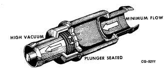
During the periods of deceleration and idle, manifold
vacuum is high. The high vacuum overcomes the force of the
valve spring and the valve bottoms in the manifold end of the
valve housing. This does not completely stop the flow but it
does restrict (Fig. 46).
Fig. 46 Plunger Position During Idle or Low Engine Speed
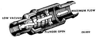
When the engine is accelerated or operated at constant
speed, intake manifold vacuum is less than at idle or during
deceleration. The spring force is stronger than vacuum pull
during this mode so the valve is forced toward the crankcase
end of the valve housing. With the valve in this position, more
crankcase vapors flow into the intake manifold (Fig. 47).
Fig. 47 Plunger Position During High Engine Speed
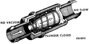
In the event of a backfire, the valve plunger is forced back
and seated against the inlet of the valve body.
This prevents the backfire from traveling through the
valve and connecting hose into the crankcase (Fig. 48). If the
backfire was allowed to enter the crankcase, it could ignite the
volatile crankcase blow-by gases.
Fig. 48 Plunger Position During Backfire or When Engine is
“OFF”.
14. Remove and Check EGR Valve and Clean or Replace,
if necessary. (V-345 and V-392 Engines Only)
a.
Remove EGR valve from engine.
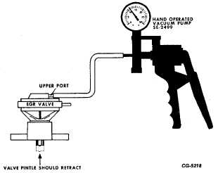
Fig. 49 EGR Valve Test
b.
Apply 10-12" vacuum to EGR valve vacuum port
(upper port of dual diaphragm valve). As vacuum is
applied, valve pintle should move off seat and retract
into valve housing (Fig. 49). If valve does not
operate when vacuum is applied, valve is faulty and
should be replaced.
c.
Visually inspect valve for evidence of valve pintle
(plunger) not seating or deposit accumulation on
pintle and seat. Clean
CGES-215 Page 27
PRINTED IN UNITED STATES OF AMERICA
|