|
| |
ENGINE DIVISION SERVICE MANUAL
TM 5-4210-230-14&P-1
engine to idle and observe position of inlet tube
damper. If damper has not rotated all or part way
down to allow some cold air to enter inlet tube,
replace temperature sensor.
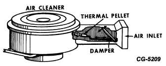
Procedure for servicing the thermal pellet type air cleaner
is as follows: (Cargostar & S-Series Vehicles)
a.
With the engine cold and ambient under hood
temperature below 32 deg. C (90 deg. F), the
damper should be closed to the cold air inlet (open to
the hot air inlet). This closed to cold air inlet can be
checked by looking in the end of the inlet.
b.
With the engine at operating temperature and the
ambient under hood temperature above 57 deg. C
(135 deg. F), thermal pellet should open the damper
allowing cold air to enter the cleaner and at the same
time shut off the hot air inlet.
Fig. 44 Pellet Type Controlled Air Cleaner
c.
If the damper does not operate as described above,
reach in the inlet, move the damper open and check
to see if it is sticking. If damper is moving freely and
the linkage is connected, then the thermal pellet must
be at fault and should be replaced.
When replacing the thermal pellet do not tighten the
pellet assembly with a tool. Tighten finger tight only.
Use locking compound on the threads to secure in
place. If a tool is used, too much pressure may be
applied changing the calibration of the thermal pellet
and linkage assembly.
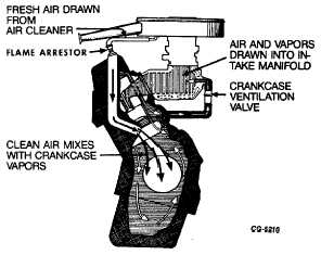
13. Check PCV System Hoses and Replace, if necessary,
Clean PCV Valve, If necessary.
a.
Remove valve from crankcase side, leaving the other
end of the valve in hose and connected to intake manifold.
b.
With the engine operating, a vacuum should be felt
at the end of the valve. If no vacuum is present, the
valve, hose and fitting should be removed and cause
of restriction determined.
c.
Check the inner chamber of the valve to see that it
can be moved freely. This may be accomplished by
inserting a stiff wire into the valve body and
observing whether or not the plunger can be readily
moved, or shake the valve and listen for rattle. If the
plunger does not move, soak in carburetor cleaner.
Fig. 45 Typical Air and Vapor Flow Through the System
13A.
Positive
Crankcase
Ventilation
Valve
(PCV)
Operation.
Since the vacuum supply for the PCV system is from the
intake manifold, the flow through this system into the manifold
must be controlled in such a manner that it varies in
proportion to the air-fuel ratio being drawn into the intake
manifold.
The PCV valve varies the amount of flow through the
system according to the various modes of operation (i.e.
CGES-215 Page 26
PRINTED IN UNITED STATES OF AMERICA
|