|
| |
ENGINE DIVISION SERVICE MANUAL
TM 5-4210-230-14&P-1
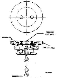
Some caps incorporate a vacuum relief valve set to open at
approximately 178 to 356mm of water (7" to 14" H20) and a
pressure relief valve set to open at approximately 508 to
1524mm of water (20" to 60" H20).
The vacuum valve provides an air intake opening to
the fuel tank. As fuel is consumed or contracts due to
cooling, causing low pressure (vacuum) in fuel tank,
atmospheric pressure opens the vacuum relief valve,
permitting air to enter the fuel tank. The pressure relief valve
acts as a pressure release in case the vapor vent system
becomes plugged. Operation of fuel tank cap vacuum relief
valve and pressure relief valves is illustrated in Fig. 19.
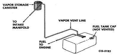
Fig. 20 illustrates a typical nonvented fuel tank cap
for vehicles with large side mounted fuel tanks.
Fuel Tank Cap Relief Valve Test
A quick check of the vacuum and pressure relief
valves in the fuel tank cap may be made as follows:
Check vacuum relief valve by applying high suction
to hole in relief valve housing (portion of cap which
enters filler neck). If vacuum relief valve fails to open
(no air flow through valve), cap should be replaced.
Fig. 20 Fuel Tank Cap (Nonvented Type)
To check pressure relief valve, force air lightly into
hole in relief valve housing. An immediate leak (air
flow) or failure to release (no air flow) indicates that
pressure relief valve is faulty and that the cap should
be replaced.
Fuel Tanks
Fuel tanks are designed to provide space to permit expansion of gasoline without overflowing. The tanks incorporate vapor
vent outlets which permit passage of gasoline vapors from the tank. Some fuel tanks have multiple vapor vent outlets located such
ahat under any sloping attitude of the vehicle at least one of the vent outlets will be above the level of the gasoline in the tank.
Evaporative loss control systems vary between vehicle models, types of fuel tanks and fuel tank installations. Systems used
on various vehicle models are illustrated in Figs. 21 thru 38.
Fig. 21 CO-1610B and COF-1810B Cargostar Vehicles With 30 Gallon Left Fuel Tank
CGES-215 Page 14
PRINTED IN UNITED STATES OF AMERICA
|