|
| |
diaphragm is faulty and the complete secondary diaphragm
assembly should be replaced.
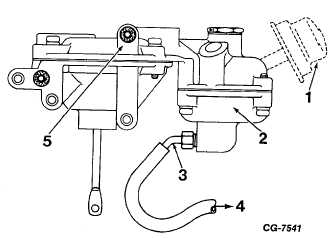
Figure 69 Vacuum Connection for Checking Secondary Control
Valve Diaphragm
1. Air Filter (Where Used)
4.
To Vacuum Source (6” G)
2. Diaphragm Chamber
5.
Not Used When Air Filter
3. Adapter Fitting
is Used
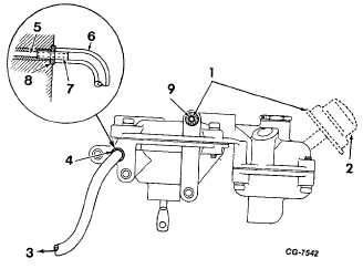
2. Connect the vacuum source to the venturi vacuum
pickup passage on the back of the cover assembly, as
shown in Fig. 70. Tightly cover the fresh air passage
also on the back of the cover assembly. Apply 6 inches
of
vacuum.
If
secondary
diaphragm
moves
(compresses spring) and vacuum holds, secondary
diaphragm is satisfactory. If diaphragm does not move
or if vacuum cannot be maintained, secondary
diaphragm is faulty P-d should be replaced.
3. With vacuum applied as in Step 2, uncover the fresh air
passage. If vacuum holds, control valve needle and
seat are satisfactory. If vacuum cannot be maintained,
control valve is faulty and the complete secondary
diaphragm assembly should be replaced.
On the Vehicle Test
The “on the vehicle” test outlined below can be used to
help locate the cause for loss of governor control.
1. With the vehicle on the service floor accelerate the
engine to check governor operation.
a. Governor should limit engine speed to 150-250 initial
overrun. Adjust governor if necessary.
Figure 70 Vacuum Connection for Checking Secondary
Control Valve and Diaphragm
1.
To Check Diaphragm Cover Passage
To Check Needle and Seat Uncover Passage
2. Air Filter
6. Hose .125 I.D.
(Where Used)
7. Tube .125 O.D.
3.
To Vacuum Source
8. Gasket
(6” HG)
9. Fresh Air Passage
4.
Venturi Vacuum Passage
5.
Vacuum Passage
NOTE:
Initial
overrun
means
that
under
acceleration the engine will momentarily exceed
governed speed by approximately 150-250 RPM
and then settle to governed speed.
b. If there is no governor control, proceed with
Step No. 2 below.
c. If the engine governs at light load and does
not govern at wideopen throttle, the problem is
probably in the secondary control valve.
Proceed with Step No. 4 below.
2. Disconnect the vacuum line (distributor to governor
throttle actuating unit) from the fitting at the governor
unit. Leave the secondary control valve vacuum line
connected. Operate the engine at 2200 RPM, wet
your finger and hold it over the opening in the fitting.
If the engine speed slows to approximately 1000
RPM, the governor trouble is in the governor control
(“spinner”) valve or the lines or connections to the
governor control valve. If the engine does not slow
down, proceed with Step No. 3.
CGES-125-T Page 44
PRINTED IN UNITED STATES OF AMERICA
ENGINE DIVISION SERVICE MANUAL
TM 5-4210-230-14&P-1
TROUBLE SHOOTING
3. Disconnect the secondary control valve vacuum line
from the fitting and remove the fitting. Again,
operate the engine at 2200 RPM and place a wet
finger over the vacuum passage in the governor
throttle
unit.
If
the
engine
now
slows
to
approximately 1000 RPM, the problem is in the
secondary control valve or its vacuum line. If the
engine does not slow down, the problem is in the
governor throttle unit or the vacuum passages behind
it.
4. When the problem is suspected to be in the
secondary control valve, operate the vehicle on the
|


