|
| |
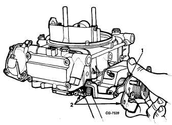
Figure 55. Accelerating Pump Lever Adjustment
1. Location of Pump Cam
2. Clearance Between Pump Lever and Adjusting Screw With
Throttle Wide Open
Accelerating Pump Stroke Adjustments
To satisfy acceleration requirements in various climates, the
accelerating pump discharge can be adjusted (Fig. 55).
The bottom hole (No. 2) in the acceleration pump cam and
the throttle lever provides the maximum pump discharge for
extreme cold weather and the top hole (No. 1) provides the
minimum pump discharge for warm weather operation. If a
change in the adjustment is required, make certain the proper
hole (top or bottom) in plastic accelerating pump cam, located
behind the throttle lever, is properly aligned (indexed) with the
numbered hole (top or bottom) in the throttle lever before
installing the retaining screw.
Dashpot
With engine temperature normalized and engine operating at
specified curb idle speed, depress dashpot plunger and
measure distance between plunger and throttle lever (see
SPECIFICATIONS). The shank of a new drill may be used to
check this adjustment.
To adjust the setting, loosen locknut and screw the dashpot in
or out as required. When the desired setting is obtained,
tighten locknut on dashpot against the bracket. Recheck idle
speed.
Throttle Modulator
With vacuum applied to throttle modulator loosen locknut and
adjust modulator until engine operates at specified RPM (see
SPECIFICATIONS).
Governor Adjustment (Spinner Type)
The procedure outlined below should be followed
when making a governor spinner adjustment. It is necessary
to use a tachometer to adjust engine RPM.
Adjust the governor spinner so that engine speed will
cut off within the engine no load cutoff range (see
SPECIFICATIONS).
1.
Turn off ignition. Engine must be completely
stopped.
2.
Remove governor clamp and gasket assembly.
3.
Turn engine over until adjusting screw whole
plug appears in the opening.
4.
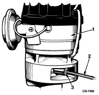
Remove plug with 1/8” Allen Wrench (Fig. 56).
Figure 56 Using Allen Wrench to Remove
Governor Plug
Fig. 56. Using Allen Wrench to Remove Governor Plug
1. Distributor 2. Allen Wrench
3. Governor Plug
5.
Insert slotted end of SE-2072-2 governor
adjusting tool firmly in hole, engaging
adjusting tang (Fig. 57). Turn the handle
clockwise to decrease speed and counterclockwise
to increase speed; ¼ turn will
change
the
speed
approximately 100 RPM.
6.
The adjusting screw is of a special design. The
spinner cannot be adjusted with a screwdriver
or
by
any
device other than this
tool.
7.
Reinstall plug with 1/8” Allen Wrench before
checking governor speed.
CGES-125-T Page 38
PRINTED IN UNITED STATES OF AMERICA
ENGINE DIVISION SERVICE MANUAL
TM 5-4210-230-14&P-1
ADJUSTMEN PROCEDURE
|