|
| |
TRUCK SERVICE MANUAL
TM 5-4210-230-14&P-1
FRAMES
Welding
Position
Amperes
Voltage
Downhand
130/140
21/23
Overhead
130/140
21/23
Vertical Up
110/120
22/24
Use low hydrogen electrodes which have superior crack
resistance and notch toughness similar to AWS-E11018. This
type electrode should be stored in a moisture-free container to
avoid porosity during welding.
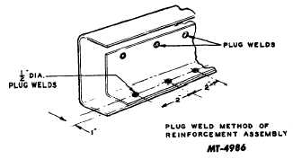
Fig. 9
Full Length Reinforcement
When heat treated frames are to be reinforced over a
greater portion of their length, frame channel reinforcements
should be installed using bolts. Bolts of high strength material
conforming to SAE grade 5 or better should be used. The
bolts and nuts should be inspected periodically and kept tight,
since the strength of the reinforcement depends somewhat on
the maximum clamping force between the members.
Drilling
The drilling of heat treated frame rails presents no
unusual difficulty. Standard high speed drills of good quality
will serve provided they are sharpened properly and not
overheated during sharpening or use. There are, however,
special high speed twist drills available having special
materials which will hold a cutting edge longer. These drills
are expensive and require especially rigid support, otherwise
drill breakage will result. When drilling heat treated rails, like
in any other drilling operation, sufficient pressure must be
applied to the drill bit to maintain continuous cutting. The drill
point should frequently be drenched with cutting oil (soluble
oil) to help cool the drill. Avoid letting a drill bit turn in the
work without cutting. To do so will usually overheat and ruin
the drill.
The drill must be held steady during the drilling operation.
Avoid wobble or change of drill angle during the drilling
operation.
Frame Straightening
When heat treated frame rails have been bent or twisted,
they should not be heated for straightening. This work should
be done with the frame rails cold. Heating for straightening
purposes is likely to destroy the rail temper in localized areas,
which will bring about rail failures.
FIFTH WHEEL MOUNTING
The following information has been prepared to avoid any
unnecessary drilling of standard non-heat treated and heat
treated frame rails, especially at the frame rail flange when
the fifth wheel is being installed.
In no instance should welding be used to attach the fifth
wheel or mounting parts to the frame rails. The application of
the weld is likely to reduce the strength of the rail in the area
of the weld. Bolts must be used throughout the fifth wheel
installation. The only exception to welding in the fifth wheel
installation is the locating block installation at each corner as
shown in Figs. 10 and 11.
Figs. 10 and 11 show two methods of mounting the fifth
wheel. Fig. 10 shows mounting where the deck plate is
attached at frame rail level. This mounting can be modified to
raise the fifth wheel; however, the mounting should be
changed to that shown in Fig. 11. The mountings illustrated
in Figs. 10 and 11 should not be utilized without the use of a
deck plate.
Low Mounting
With reference to this type mounting Fig. 10 shows the
various details to follow. Note that the drawing shows a 4 x 3-
1/2" mounting angle at the frame rail which is cut out at the
spring hanger to provide 1/8" clearance.
Where rivets are present the mounting angles must be
drilled to provide clearance for rivet heads (C on drawing).
This applies to rivets in the frame flange as well as frame
side.
Bolts must be used throughout the installation of the fifth
wheel mounting. However, locating blocks can be welded to
the mounting angles as shown in Fig. 10. These blocks must
be welded in place before the angles are installed on the
frame rail.
CTS-2037-HA Page 7
PRINTED IN UNITED STATES OF AMERICA
|

