|
| |
TRUCK SERVICE MANUAL
TM 5-4210-230-14&P-1
FRAMES
b.
Preheat the frame rail along the crack area to
500-600 degrees to burn off excess oil or paint
then permit heated area to cool to 200
degrees or below before welding is started.
Under no circumstances should the rail be
heated to a temperature exceeding 900-950
degrees F. since this is the tempering
temperature of the rail.
c.
Either alternating current or direct current
reversed polarity, combined with a short arc
and a beading or narrow weave technique
may be used. Direct current reversed polarity
is recommended or preferred.
d.
Slag should be removed after each pass and
an interpass or constant temperature of 200
degrees should be maintained.
e.
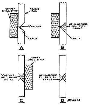
When sufficient metal has been deposited, the
weld bead should be ground flush, Fig. 7, with
the surface being repaired.
Fig. 7.
f.
Where both sides of the frame rail are
accessible, a V-groove is ground from the side
opposite the repair and the procedure outlined
above
repeated.
Dependent
upon
accessibility, "chill" strips should be used
wherever possible. The V-groove ground on
the opposite side
of the repair should be deep enough to enter the sound metal
of the first weld repair "C" of Fig. 7.
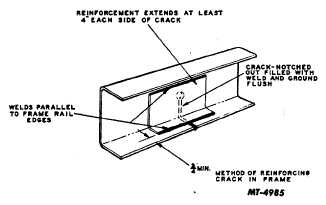
Frame
Welds on heat treated material tend to reduce physical
properties in the weld heat-affected zone. Because of this, it
is recommended that all reinforcements be designed so that
all welds are parallel, rather than perpendicular to the frame
rail edges. Welds perpendicular to the flange edges will
reduce the carrying capacity of the rail, Fig. 8 and 9.
Fig. 8
The edge of the reinforcement flange to the edge of side
rail flange dimension should be held to a minimum of three
quarters of an inch to keep the heat-affected zone from
extending to the sidemember flange edge. Wherever
possible, it is recommended that plug welds of the type shown
in Fig. 9, be substituted for edge welds when assembling the
reinforcement to the side rail. Plug welds offer the
advantages of a reduced heat-affected zone plus increased
flexibility and reduced stress concentrations. When using this
method, one half inch (minimum) diameter holes should be
drilled and chamfered in the reinforcement on 2" center to
center distances. At no time should these holes be drilled in
the frame rail being repaired. The reinforcement should then
be installed in its proper position on the sidemember and the
holes filled with weld material.
Again
a
minimum
dimension
of
3/4"
should
be
maintained between the weld and the edge of the sidemember
flange. The voltage, amperage and pre-heat specifications
listed below should be followed.
CTS-2037-A Page 6
PRINTED IN UNITED STATES OF AMERICA
|