|
| |
ENGINE DIVISION SERVICE MANUAL
TM 5-4210-230-14&P-1
ENGINE
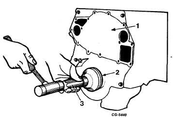
NOTE: With the engine front cover assembled to the
cylinder block, a new oil seal can also be installed using
SE-1949 installer as shown in Figure 148. Install oil seal
flush to .010" below front face of front cover.
Fig. 148 Installing Engine Front Cover Oil Seal with Cover
Assembled to Cylinder Block Using SE-1949
Installer
1. Front cover
2. Oil seal
16. Position a new front cover gasket to the cylinder block
and install the engine front cover assembly. Dowel pins
are provided for proper alignment.
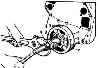
17. Install woodruff key in the crankshaft and install the
crankshaft vibration damper using SE-1900 installer and
SE-1900-18 adapter, Figure 149, with thrust bearing to
reduce friction. Install damper bolt and washer and
tighten to specified torque. See "Torque Chart."
18. Install crankshaft pulley on vibration damper with bolts
and lockwashers. Tighten to specified torque. See
"Torque Chart."
19. Install oil pump, pick-up tube and screen assembly.
Check alignment of pump to cylinder block for free
movement of oil pump shaft. There should be no bind if
the pump is correctly aligned.
20. Place the flywheel in position on the crankshaft. Apply
sealing compound not affected by oil to the threads of the
flywheel mounting bolts. Avoid getting sealing compound
on mating
surfaces of flywheel and crankshaft. Install mounting
bolts to specified torque.
Fig. 149 Installing Crankshaft Vibration Damper
Using SE-1900 Installer and SE-1900-18
Adapter
1. Damper
3. Thrust bearing
2. Sleeve
4. Nut
21. Install the clutch pilot bearing into the flywheel. To
assure the clutch pilot bearing does not rotate in the
flywheel bore, it is recommended that Loctite grade B be
applied evenly around the O.D. of the bearing and the
I.D. of the flywheel bore at the time of installation. Do
not allow Loctite to contact inside of bearing or between
flywheel and crankshaft.
After the Loctite grade B has been applied, allow to cure
for 1 to 2 hours. The interval required to reassemble the
vehicle from the point of clutch bearing is considered
adequate for the curing of Loctite.
22. Place the clutch driven disc against the flywheel so the
long portion of the hub is toward the rear. Place the
clutch in position on the flywheel over the clutch driven
disc, install two or three mounting bolts and lockwashers
loosely. Install a clutch aligning arbor, if available, or a
transmission main drive gear shaft, Figure 150, through
the clutch driven disc hub spline and into the clutch pilot
bearing. Hold the clutch driven disc in position while
completing installation of the remaining mounting bolts
and lockwashers in the flange of the clutch backing plate
or cover. Tighten all bolts
CGES-210 Page 60
PRINTED IN UNITED STATES OF AMERICA
|


