|
| |
ENGINE DIVISION SERVICE MANUAL
TM 5-4210-230-14&P-1
ENGINE
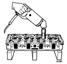
will be necessary to grind from the top and/or bottom of the
seat until the proper seat width is obtained using grinder
SE1631, Figure 115.
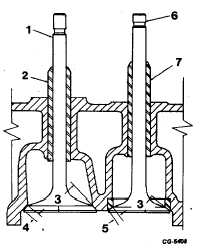
Fig. 114 Sectional View of Valves
1.
Intake valve
2.
Intake valve guide
3.
Angle
4.
A
5.
B
6.
Exhaust valve
7.
Exhaust valve guide
Fig. 115 Grinding Seats Using SE-1631 Grinder
Use a 60
angle grinding stone to remove stock from
the bottom of the seat (raise seat). Use a 30
angle stone to
remove stock from the top of the seat (lower seat).
After
the
seat
grinding
operation
has
been
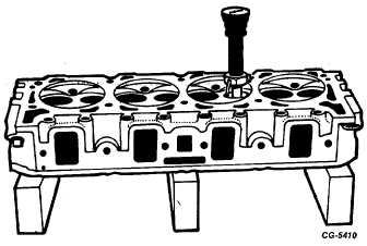
performed, it is necessary to check the seat for run-out, Figure
116. Seat run-out should not exceed limits as shown in
specifications.
Figure 116 Using Gauge from SE-1631 Tool Grinder Set for
Checking Seat Run-Out
It is important to have the finished seat face contact
the approximate center of the valve face. Position the valves
in the cylinder head. Place a thin coat of Prussian Blue on
each valve face and tap the valve lightly to its seat.
NOTE:
This is merely for test and proof of results
of refacing and reseating operations. A
poor grind job cannot be corrected by
lapping. Use of lapping compounds is not
recommended. A nearly perfect seat
often-times is destroyed by attempting to
lap the valves to their seats. Inspect each
valve for seat dimensions as outlined in
specifications and make any necessary
corrections.
The
corrections
should
always be made on the seat and not the
valve face.
NOTE:
New valves need not be refaced; however,
all valves should be carefully inspected for
damaged seat faces or for a run-out
condition due to a bent valve stem. Use
SE-2614 tool to determine the condition of
the valve.
If the ends of the valve stems are grooved or scored,
they may be ground to true up; however, remove only a
minimum amount of material. Rechamfer as necessary.
Wipe valve faces and valve seats with a cleaning
solvent to remove all dirt or foreign material. Coat the valve
stems and faces with oil and install the valves in the same
seats to which they were checked. On the exhaust valves,
install the Roto-Cap assembly, valve spring, valve stem
damper, valve stem seal and
CGES-210 Page 42
PRINTED IN UNITED STATES OF AMERICA
|


