|
| |
ENGINE DIVISION SERVICE MANUAL
TM 5-4210-230-14&P-1
ENGINE
surfaces for scratches or mars which could cause leakage
after assembly. The use of holding fixture SE-1939 reduces
the chances of gasket surface damage.
Check the gasket surface of the cylinder head for
trueness with a straightedge. Test by attempting to insert a
.003" feeler gauge ribbon between the straightedge and
cylinder head. If this is possible, either resurface or replace
the cylinder head.
NOTE:
When resurfacing the cylinder head, do
not remove more than .005" material.
Cylinder head height measurement should
be taken between the machined surface of
the head and the machined surface of the
bolt bosses on the exhaust manifold side
of the head. The original specification for
this measurement is 3.282" + .010".
The cylinder head assemblies and head gaskets are
interchangeable from one cylinder bank to another.
To disassemble the valve assembly, turn the head
assembly in a vertical position either on a clean work bench or
using SE-1939 cylinder head holding fixture as a cradle to
hold the assembly.
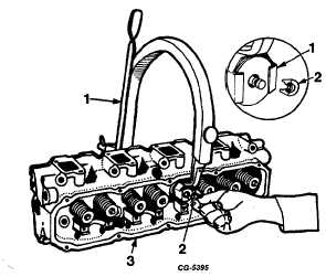
Apply a valve spring compressor and remove the
valve keepers or locks, Figure 102. Remove the spring
compressor and disassemble the spring retainer, valve stem
seal and Roto-Coil assembly from the exhaust valves.
Remove the spring retainer, valve stem damper, spring, valve
stem seal and valve spring seat from the intake valves. All
valves are removed in
Fig. 102 Removing Valve Keepers
1.
Valve spring compressor
2.
Keepers
3.
Cylinder head
the same manner. Keep valves and their related parts
together so they may be reinstalled. in their respective
positions.
NOTE:
It may be necessary to strike the valve
ends with a light, soft hammer to break the
valve keepers loose.
Remove all carbon from valve stems and head using
a fine wire brush or buffing wheel. Inspect each valve,
discarding any that show evidence of burned, warped or bent
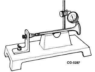
condition. SE-2614 valve gauge, Figure 103, or similar tool
can be used for checking stem straightness and seat run-out.
Fig. 103 Checking Valve Stem Straightness and Face Run-
Out
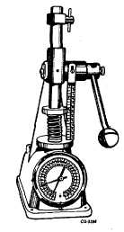
Fig. 104 Checking Spring Tension Using SE-2241 Tester
CGES-210 Page 38
PRINTED IN UNITED STATES OF AMERICA
|