|
| |
ENGINE DIVISION SERVICE MANUAL
TM 5-4210-230-14&P-1
ENGINE
Connect the battery ground strap and fill the cooling
system to the specified level. Fill the engine crankcase with
specified engine oil to the proper level. Refer to the
Operator's Manual for this information. However, if equipped
to prime the lubricating system, refer to "Lubrication System
Priming" and follow the procedure described.
Check accessory and pulley drive belts and adjust if
necessary.
Start engine and operate all controls through their full
range to check for proper adjustment.
Inspect all hose connections for coolant leaks and air
connections for air leaks.
ENGINE DISASSEMBLY
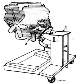
Install the engine in the SE-1962 Overhaul Stand with
mounting plate, Figure 10.
Fig. 10 Engine Installed in SE-1962 Overhaul Stand With
Mounting Plate
1. Engine stand
2. Mounting plate
NOTE: Use of this overhaul stand permits raising or
lowering (vertical to horizontal position) the engine as
required to permit rotating the engine 360°
and is held
securely in any of the eight positions provided . However,
before engine rotation is performed, it is recommended
the engine be stripped of as many components as
possible to eliminate excessive weight and provide
clearance. The engine can be raised in a vertical position
over the pedestal of the stand and the pin released and
crankcase rotated and locked in any one of the eight
positions.
1.
Make sure all oil and water have been drained from the
cylinder block.
2.
Remove fan blade with spacer and front engine mount.
3.
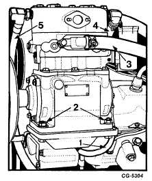
Disconnect water inlet, water outlet, air inlet and oil
feed lines from air compressor, Figure 11.
Fig. 11 Air Compressor Removal
1. Oil feed line
4. Water inlet line
2. Nuts
5. Water return line
3. Air inlet line
4.
Loosen four nuts on bracket and slide compressor
inward, Figure 11. Remove V-belt and water pump
front pulley.
5.
Remove nuts, bolts and flat washers from bracket and
remove air compressor with gasket. Remove water
inlet and outlet hoses.
6.
Remove
bolts
and
lockwashers
securing
air
compressor bracket to the engine, Figure 12. Remove
bracket with "O" ring.
7.
Loosen alternator adjusting strap bolt and mounting
bolt, Figure 13. Remove two V-belts.
8.
Remove alternator adjusting strap bolt and mounting
bolt with flat washers. Remove alternator from bracket.
9.
Remove alternator bracket and adjusting bracket by
removing bolts and flat washers, Figure 14.
CGES-210 Page 10
PRINTED IN UNITED STATES OF AMERICA
|