|
| |
TRUCK SERVICE MANUAL
TM 5-4210-230-14&P-1
ELECTRICAL
the current to the affected circuit is rapidly interrupted and
restored until the short is located and corrected. Protection
against destruction of the wiring is thereby provided and
possible rapid discharge of the battery averted.
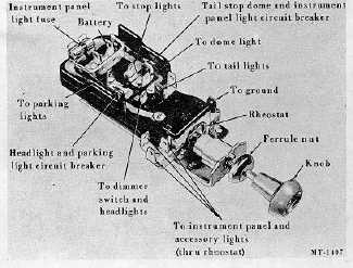
When the switch control knob is pulled out to the first
position, an internal circuit is established to the switch
terminals for the parking lights, instrument lights and taillights.
When the knob is pulled out to the last position, a circuit is
established to the switch terminals for the headlight s,
instrument lights and tail lights. The current for the
instrument lights passes through a rheostat which is regulated
by the light switch knob. By turning the switch knob
clockwise, the instrument lights can be dimmer or turned off
completely. The cab interior light (except CO and VCQ
models) may be turned on while retaining use of the
instrument panel lights by rotating the lighting switch knob to
the extreme counter clockwise position (through the detent or
"click").
Fig. 4
Removal
1.
Pull light switch knob outward to headlight position.
2.
Depress shaft release button, on switch body and
pull switch knob and shaft out of switch body.
3.
Remove ferrule nut by positioning a screw driver in
the end, turn nut in a counterclockwise direction.
4.
Disconnect all wires from the lighting switch and
either tag them for correct installation or note the
relation of each wire to its proper terminal.
CTS-2293N Page 4
PRINTED IN UNITED STATES OF AMERICA
|