|
| |
TRUCK SERVICE MANUAL
TM 5-4210-230-14&P-1
ELECTRICAL
LIGHTING SWITCH (LESS PROTECTION FUSE BUT
EQUIPPED WITH A CIRCUIT BREAKER).
Description And Operation
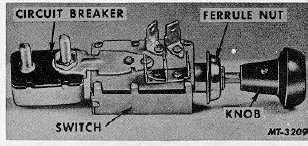
The lighting switch illustrated in Figure 1 does not
incorporate fuses in the switch assembly, but is protected by a
circuit breaker.
When the lighting switch knob is pulled out to the
first position, the parking lights, tail lights and instrument
lights are on. When the lighting switch knob is pulled out to
the last position, all lights are on.
Fig. 1.
Removal
1.
Pull light switch knob outward to headlight position.
2.
Loosen Allen screw in knob and remove knob from
shaft.
3.
Remove furrule nut.
4.
Disconnect all wires from the switch. Tag wires for
proper installation.
LIGHTING SWITCH (LESS PROTECTION FUSE AND
CIRCUIT BREAKER).
Description and Operation
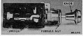
This type lighting switch, Fig. 2, does not
incorporate a circuit breaker or fuses as the lighting system is
protected by a fuse panel.
Fig. 2.
The lighting switch on the instrument panel controls
the headlights, parking lights, instrument panel lights, cab
interior light and tail lights. When the lighting switch is pulled
out halfway, both parking and tail lights are "on". To light the
instrument panel, turn the light switch control to the left; a
built-in rheostat controls the intensity of the panel light from
"off" to full "on". To turn the cab interior light on, turn the
lighting switch control counterclockwise to the extreme left
position.
Removal
1.
Pull light switch outward to headlight position.
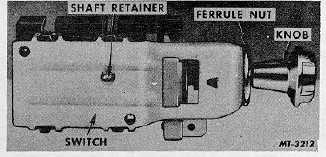
2.
Depress shaft release button, Fig. 3, on switch body
and pull knob and shaft out of switch body.
3.
Remove ferrule nut by positioning a screw driver in
the end, turn nut in a counterclockwise direction.
4.
Disconnect all wires from the lighting switch and
either tag them for correct installation or note the
relation of each wire to its proper terminal.
Fig. 3.
LIGHTING SWITCH (WITH PROTECTION FUSE AND
CIRCUIT BREAKER).
Description and Operation
This type lighting switch, Fig. 4, incorporates 15
amperes dual thermal circuit breakers and a fuse to protect
the entire lighting system. One circuit breaker protects the
headlights and parking lights, while all other lights on the
vehicle are directed through the remaining circuit breaker. In
addition, the panel lights are also protected by a (4 amp) fuse.
This type of circuit permits the use of the headlights to be
retained if an overload or short develops in another part of the
system. A current flow of more than 15 amperes will cause
the points of this current limit relay to open and close as they
warm and cool. Thus
CTS-2293 Page 3
PRINTED IN UNITED STATES OF AMERICA
|