|
| |
TRUCK SERVICE MANUAL
TM 5-4210-230-14&P-1
ELECTRICAL
c.
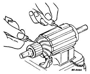
Grounds in the armature can be found using a
test lamp and prods, Fig. 9. If the lamp lights
when
one
prod
is
positioned
on
the
commutator and the other prod on the
armature core or shaft the armature is
grounded.
Fig. 9 Testing Armature for Grounds
If the commutator is worn, dirty, out-of-round or the
insulation is high, the commutator should be turned
down and under cut.
3.
Field Coils: Check field coils for grounds and opens
with a test lamp.
a.
Grounds:
With
the
field
coil
ground
disconnected, position one test prod on the
field frame and the other to the field
connector. If the lamp lights the field coils are
grounded and must either be replaced or
repaired.
b.
Opens: If the test lamp does not light when
the prods are connected to the ends of the coil
leads, field coils are open.
A pole shoe spreader and pole shoe screw driver
should be used if the field coils are to be removed. Extra
caution should be taken in replacing the field coils to prevent
grounding or shorting when they are tightened in place. If the
pole shoe has a long lip on one side, it should be assembled
in the direction of armature rotation.
REASSEMBLY
1.
Place the clutch assembly on the armature shaft.
2.
To aid in reinstalling the snap ring and retainer on
the armature shaft, proceed as follows.
a.
Place the retainer on the armature shaft with
the cupped surface facing the snap ring
groove.
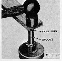
b.
Place the snap ring on the end of the shaft.
With a piece of wood on top of ring, force the
ring over the shaft with a light hammer blow,
Fig. 10; then slide the ring down into the
groove.
Fig. 10 Installing Snap Ring
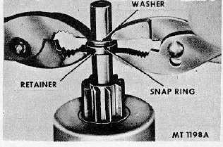
c.
To force the retainer over the snap ring, place
a suitable washer over the shaft and squeeze
the retainer and washer together with pliers,
Fig. 11.
d.
Remove the washer.
Fig. 11 Installation of Retainer And Thrust Collar
CTS-2258-K Page 8
PRINTED IN UNITED STATES OF AMERICA
|