|
| |
TRUCK SERVICE MANUAL
TM 5-4210-230-14&P-1
ELECTRICAL
DISASSEMBLY
If the starting motor does not perform according to
the specifications, it will be necessary to disassemble it for
further tests of the components.
1.
Disconnect the field coil connections from the
solenoid motor terminal.
2.
Remove the thru-bolts.
3.
Remove the commutator end frame and field frame
assembly.
4.
Remove the armature assembly from the drive
housing. On some models it will be necessary to
remove the solenoid and shift lever assembly from
the drive housing before removing the armature
assembly.
5.
Remove the thrust collar from the armature shaft.
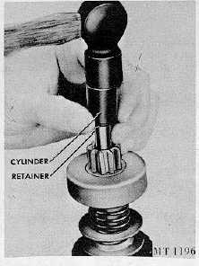
6.
Remove the pinion from the armature by sliding a
metal cylinder onto the shaft; with a hammer striking
the metal cylinder against the retainer, drive the
retainer toward the armature core and off the snap
ring, Fig. 7.
Fig. 7 Removing Retainer from Snap Ring
7.
Remove the snap ring from the groove in the
armature shaft.
8.
Roll type clutches are designed to be services as a
complete unit; therefore, do not disassemble. If the
condition of the clutch assembly is questionable,
replace it.
INSPECTION AND REPAIR
1.
Brushes and Brush Holders: Inspect the brushes for
wear. If they are worn down to one-half their original
length, when compared with a new brush, they
should be replaced.
Clean brush holders and be sure that the brushes will
not bind in the holders. The full length of the brush
surface should ride on the commutator with the
proper spring tension (see specifications) to provide
a good contact. Inspect the brush leads and screws
to be sure they are tight and clean.
2.
Armature: Inspect the armature to be sure there are
no short circuits, opens, or grounds.
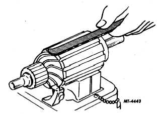
a.
Short circuits are located by turning the
armature in a growler while holding a steel
strip on the armature. The steel strip will
vibrate on the area of the short circuit, Fig. 8.
Fig. 8 Testing Armature for Short Circuits
b.
Opens are usually found where the conductors
are joined to the commutator. Loose or poor
connections will cause arcing and burning of
the commutator. If the bars are not burned
too bad, resoled the leads in the riser bars and
turn the commutator down in a lathe. Then
under
cut
the
insulation
between
the
commutator bars 1/32".
CTS-2258-K Page 7
PRINTED IN UNITED STATES OF AMERICA
|