|
| |
TRUCK SERVICE MANUAL
TM 5-4210-230-14&P-1
ELECTRICAL
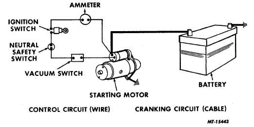
Fig. 3 Starting Motor Circuit
Excessive resistance in the starting or cranking
system circuit will cause slow cranking speeds and hard
starting. The starting system will function properly only when
the "cranking circuit" and "control circuit" with the components
are in satisfactory condition. Corrosion, loose terminal,
damaged or undersized cables (wires) will cause cranking
problems. In addition, the switches involved must make good
electrical connections when closed.
The voltage drop test will be performed in three
steps: cranking circuit, control circuit and grounded side.
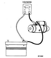
Cranking Circuit: Voltage drops are measured by
connecting a voltmeter in parallel across the circuit or section
of a circuit being inspected, then reading the voltmeter while
circuit is in operation. To test voltage drop in the cranking
Fig. 4 Cranking Circuit Test
circuit from battery to starter, connect the voltmeter
(observing the polarity and voltage rating of meter) to battery
post (not clamp) to starter motor terminal as shown in Fig. 4.
Prevent engine from starting during test. Crank engine and
observe voltmeter reading.
Values of maximum voltage drops for a standard 12-
volt cranking circuit are as follows:
Cable under three (3) feet.......................
.1 volt
Cable over three (3) to six (6) feet ..........
.2 volt
Mechanical Switch . ...............................
.1 volt
Solenoid Switch .....................................
.2 volt
Magnetic Switch ....................................
.3 volt
Each Connection....................................
.0 volt
Add these values together on the particular chassis
being inspected. For example, if your total of the values from
the chart is .5 volt and you have less than .5 volt drop on the
chassis, continue to grounded side test.
However, if there is more than .5 volt drop you have
an excessive voltage drop and this must be located by moving
test lead from starting motor and working toward the battery.
Crank engine with each move. When a noticeable decrease
in the voltage reading is obtained, the trouble will be located
between that point and the preceding point checked.
Items which could be at fault can either be a
damaged cable or poor connection, an undersized wire or
possibly a bad solenoid (contact within the solenoid). Repair
the fault.
CTS-2258-K Page 5
PRINTED IN UNITED STATES OF AMERICA
|