|
| |
TRUCK SERVICE MANUAL
TM 5-4210-230-14&P-1
ELECTRICAL
2.
Bushings should be coated with a medium grade of
engine oil.
3.
The armature shaft should be coated lightly with a
medium grade of engine oil.
4.
The drive assembly should be wiped clean.
CAUTION:
Do not clean in any degreasing tank or with
grease dissolving solvents, this will dissolve
the lubricant in the clutch mechanism.
5.
Relubricate the sprag clutch with a medium grade of
engine oil.
CAUTION:
Avoid excessive lubrication.
TROUBLE SHOOTING THE STARTING MOTOR CIRCUIT
When trouble develops in the starting motor system, and
the starter motor cranks the engine slowly or not at all, several
preliminary checks can be made to determine whether the
trouble is in the battery, starting motor, wiring circuit between
them, or elsewhere. Many conditions besides defects in the
motor can result in poor cranking performance.
To obtain full performance from a starting motor or to
determine the cause of abnormal operation, the motor should
be subjected to one or more of the following tests. Failure of
the motor to perform according to the specifications will
require removal of starter and disassembly and further checks
or adjustments made.
NOTE:
All starting motor tests should be made with
engine and battery at room temperature (not
cold).
Regardless of the construction, never operate the
starting motor more than 30 seconds at a time without
pausing to allow it to cool for at least 2 minutes. Overheating,
caused by excessive cranking, will seriously damage the
motor.
For the most part a volt-ampere tester (SE2283) will be
used in performing the starter tests and the instruction manual
supplied with the tester will provide the detailed instructions
using the volt-ampere tester.
NOTE:
All illustrations of starting motor and circuit
tests show leads connected for NEGATIVE
grounded system. Reverse the positions of
the leads when testing a POSITIVE grounded
system. Make sure the volt selector switch on
the volt-ampere tester is positioned properly
for the voltage system being inspected.
Test No. 1 -- Cranking Voltage Test
This test tells us the overall condition of battery, starter,
cables or switches to determine if sufficient voltage is
available to operate ignition system when starter is in
operation.
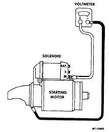
Connect voltmeter leads at the starter observing the
polarity, Fig. 2. Disconnect secondary coil lead to prevent
engine from starting. Crank engine noting voltmeter reading
(should be 9. 6 volts or better with 12-volt electrical system).
If a reading of less than 9.6 volts is found, proceed to
the next tests.
Fig. 2 Cranking Voltage Test
Test No. 2 -Battery Capacity Test
The battery capacity test is performed to determine if
the battery is in satisfactory condition. See "Battery" Section.
If the battery passes this test, continue the next test.
Test No. 3 -Voltage Drop Test
Generally, the starting or cranking circuit is a series
circuit from the battery insulated post to the starting motor
solenoid, to the motor, to ground (chassis) and return to the
battery ground post, Fig. 3.
In the cranking circuit we also have a cranking control
circuit, Fig. 3. In this circuit the solenoid is controlled or
operated by closing an ignition switch or push button starting
switch at the instrument panel. In this cranking control circuit
there
are
frequently
some
safety
switches
such
as
transmission "neutral safety switch" and/or vacuum operated
cutout switch.
CTS-2258N Page 4
PRINTED IN UNITED STATES OF AMERICA
|