|
| |
TRUCK SERVICE MANUAL
TM 5-4210-230-14&P-1
ELECTRICAL
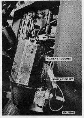
Fig. 18 Ashtray Light
6.
Discard old light assembly.
7.
Hold lens in hole in ashtray housing and snap new
light assembly over lens to retain lens and light
assembly.
8.
Connect light assembly wiring connector to wiring
harness connector.
9.
Position cluster panel (with ashtray housing, radio,
etc.) on instrument panel and secure with screws.
10.
Position ashtray in ashtray housing.
11.
Check light operation.
HEATER/AIR CONDITIONING CONTROL LIGHT
BULB REPLACEMENT
1. Remove
control
assembly
mounting
screws.
Remove trim plate. Pull control assembly outward.
It may be necessary to remove ashtray to allow
movement of control assembly.
2.
Rotate light socket (Figure 19) clockwise (as viewed
from rear of vehicle). Pull light socket (with bulb) from control
assembly.
Fig. 19 Heater/Air Conditioning Control Light
3.
Grasp bulb and pull straight outward to remove plug-
in type bulb from socket.
4.
Insert new bulb into socket.
5.
Insert light socket into control assembly. Turn light
socket to secure in position.
6.
Position control assembly in instrument panel and
install trim plate and mounting screws.
7.
Check light operation.
AUTOMATIC TRANSMISSION CONTROL LIGHT
BULB REPLACEMENT
1.
Grasp light socket and disengage socket from hole in
control housing. DO NOT pull on wire to remove
socket. (See Figure 20).
In some cases it may be necessary to loosen control
assembly left support bracket bolts to permit removal
of light socket.
2.
Press bulb in lightly and turn counterclockwise to
disengage retaining pins.
3.
Pull bulb from socket.
4.
Install new bulb as follows:
a.
Align retaining pins with slots in socket.
b.
Push bulb into socket and turn clockwise to
secure retaining pins.
5.
Insert light socket into hole in control housing and
push inward until retaining clips "snap" into position
securing socket.
CTS-2781S Page 11
PRINTED IN UNITED STATES OF AMERICA
|