|
| |
TRUCK SERVICE MANUAL
TM 5-4210-230-14&P-1
ELECTRICAL
To adjust headlight aim, turn adjusting screws as required to
position headlight beam pattern as shown under HEADLIGHT
AIMING. Adjustments can be made without removing
headlight bezels.
SEALED BEAM UNIT REPLACEMENT
1.
Remove four (4) retaining screws (Figure 3) and
remove headlight bezel.
Fig. 3 Removing Headlight Bezel
2.
Remove three (3) retaining screws and remove
sealed beam unit retaining ring (Figure 4).
Fig. 4 Removing Sealed Beam Unit Retaining Ring
3.
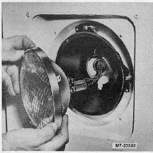
Pull sealed beam unit from headlight assembly.
Disconnect three-way wiring connector from rear of
sealed beam unit (Figure 5) and remove sealed
beam unit.
Fig. 5 Removing Sealed Beam Unit
4.
Connect three-way wiring connector to new sealed
beam unit.
5.
Position sealed beam unit in mounting ring. Install
retaining ring and secure with screws.
6.
Install headlight bezel and secure with screws.
CAUTION
DO NOT overtighten bezel retaining screws.
Overtightening
could
cause
damage
(stripping) of threads in hood (fender).
7.
Check light operation.
HEADLIGHT ASSEMBLY REPLACEMENT
1.
Remove four (4) retaining screws and remove
headlight bezel (Figure 3).
2.
Disconnect headlight retaining spring from headlight
assembly (Figure 6).
3.
Disengage headlight assembly from adjustment
screws. DO NOT turn adjustment screws.
CTS-2781S Page 4
PRINTED IN UNITED STATES OF AMERICA
|