|
| |
TM 5-4210-230-14&P-1
VEHICLE OPERATION
BRAKE ANTILOCK MONITOR (Warning) LIGHT
A satisfactory antilock system is indicated each time
the ignition key switch is turned to either "ON" or "RUN"
position
with
the
antilock
warning
light
momentarily
illuminating, followed by the light going out and remaining off.
If the warning light should remain "ON" a problem is
indicated in the antilock control system. Should this condition
occur, the service brakes will function in the normal manner;
however, the vehicle will not have the added safety and
advantage of the antilock.
If the antilock warning light comes on and stays on, the
antilock system should have an "Ignition Cycle Check"
performed to determine if all or any computer modules and air
control valves are operating satisfactorily. Refer to VEHICLE
MAINTENANCE "Brake Antilock System" for Ignition Cycle
Check.
As the vehicle is driven about 24 km (15 mph) the
antilock warning light should remain "OFF". If the light should
come "ON" and remain on above 24 km (15 mph), a wheel
sensor problem may exist. Excessive spin on one drive wheel
relative to the other on some axles may cause the monitor
light to go "ON". To correct this condition, the ignition switch
must be turned "OFF" and back "ON" to reset the system and
correct the condition.
If wheel spin is not the cause of the light remaining on,
one or more of the sensors could be the problem. Refer to
VEHICLE MAINTENANCE "Brake Antilock System" for quick
trouble shooting of antilock system.
BRAKE PEDAL
When making a stop for a traffic light or going down a
long grade, do not "fan" the air brake pedal as this wastes air
pressure. On long grades, use snubbing "on-off" brake
application to reduce the possibility of extreme heat and wear
to the brake lining. A good policy to follow is to downshift
your vehicle on long grades to obtain maximum engine
assistance in reducing vehicle speed. The best way to make
a stop is to apply the brakes as hard at first as the road and
load conditions will permit and then gradually reduce the
pressure, so that at the end of the stop there is sufficient air
pressure to hold the vehicle.
BRAKES PARKING
If both air systems fail or are depleted the spring
brakes apply.
To release, repair air leak and recharge system to 483
kPa (70 psi). If leak cannot be repaired and the vehicle must
be moved, the spring brake must be manually released.
CAUTION
To avoid personal injury or property damage
when manually releasing the spring brakes,
be sure to block the wheels so that vehicle
cannot move when the brakes are released.
For
towing,
make
sure
the
vehicle
is
connected or secured to tow vehicle before
releasing the spring brakes.
BRAKE RELEASE (Parking)
ANCHOR LOK SPRING BRAKE
In the event it is necessary to move the vehicle after an
emergency application (before air pressure can be restored),
the
emergency
parking
spring
can
be
compressed
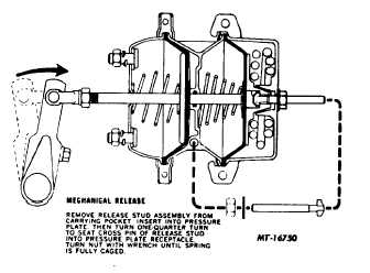
mechanically to release the brake. A release stud "spring
caging tool" is furnished with the brake chamber assembly.
The release stud engages in the spring pressure plate and its
nut is tightened to compress "cage" the spring and release the
brake.
Apply a light coat of Never Seeze to the threads of the
release stud to avoid any unnecessary wear of the threads.
Remove the access plug from the end of the spring chamber.
Insert the release stud through the opening in the chamber
and into the spring pressure plate.
Turn the release stud 1/4 turn to engage the tangs on
the release stud into the slot in the pressure plate. Install the
nut on the release stud. Be sure tang on release stud stays
engaged with slot on pressure plate while installing the nut.
Tighten the nut with a wrench to compress the spring.
2
|