|
| |
ENGINE DIVISION SERVICE MANUAL
TM 5-4210-230-14&P-1
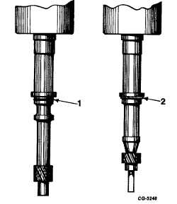
Fig. 7
1.
"O" Ring
2.
Gasket
DISTRIBUTOR SHAFT AND BUSHING WEAR TEST
This procedure can be used to check condition of the
distributor shaft and shaft bushings in the distributor housing.
1.
Clamp distributor in a vise equipped with soft jaws and
apply only enough pressure to restrict movement of
distributor.
2.
Remove distributor rotor and dielectric shield (dust
cover).
3.
Attach dial indicator to distributor housing so that
indicator plunger rests against top portion of trigger
wheel assembly (Figure 8). C20
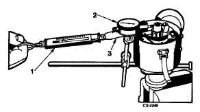
Fig. 8 Shaft and Bushing Wear Test (Checking Distributor
Shaft Side Play)
1. Spring Scale
2. Dial Indicator
3. Wire Loop
4.
Place one end of a wire loop around top of trigger
wheel assembly (rotor shaft). Hook a spring scale in
other end of wire loop and pull on a line with plunger of
dial indicator (Figure 8). Wire loop must be
perpendicular to shaft to assure a a straight pull.
Also, loop must not interfere with dial indicator
mounting bracket.
5.
Apply one-half (½ ) pound of pull on spring scale and
read movement of plunger on indicator dial. Apply
one-half (½ ) pound of pull in opposite direction and
again read movement on indicator. Peak-to-peak side
play is the sum of these two readings.
If distributor shaft side play exceeds maximum
permissible
limit
(see
DISTRIBUTOR
TEST
SPECIFICATIONS), replace distributor shaft bushings
(see Distributor Housing Bushing Replacement).
DISTRIBUTOR OPERATION TEST
(On Test Stand)
Operation of the distributor can be checked on a
distributor test stand.
It is advisable to perform the distributor operation test
prior to disassembly of the distributor for service. This test will
give valuable information about the condition of the distributor
and indicate where parts replacement may be required.
Preparation of Distributor Test Stand
(Refer to Figure 9)
Additional equipment required:
Battery, 12 volt (fully charged).
Jumper Wires (2) with clips at each end.
1.
Mount distributor to be tested in test stand.
2.
Clip test stand distributor lead to ring connector on
brown distributor lead.
3.
Clip test stand ground lead to ground stud on
distributor mounting frame.
CGES-145-U Page 6
PRINTED IN UNITED STATES OF AMERICA
|