|
| |
ENGINE DIVISION SERVICE MANUAL
TM 5-4210-230-14&P-1
Trigger wheels of distributors for four-cylinder engines
have four (4) teeth. Distributors for eight-cylinder engines
have eight (8) teeth on the trigger wheel.
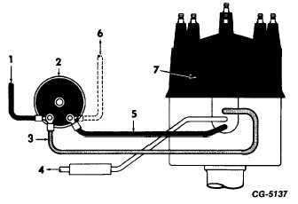
Distributor primary wiring consists. of two leads
connected to the ignition coil primary terminals. The red wire
from the distributor connects to the coil positive (+) terminal.
The brown wire from the distributor connects to the coil
negative (-) terminal. (See Figure 4). A third (white) wire
from the distributor connects to the deceleration throttle
modulator (DTM), where used. Because primary (low voltage)
current is regulated within the electronic control unit, a ballast
resistor or resistance wire is not required in the primary
circuit.
Fig. 4 Distributor Primary Wiring
1.
From ignition switch
2.
Ignition coil
3.
Red wire
4.
To decelerate throttle modulator (where used)
5.
Brown wire
6.
To governor control unit (where used)
7.
Distributor
The secondary (high voltage) components are: coil
tower, distributor cap, rotor, high tension cables and spark
plugs. The new distributor cap featuring superior physical and
dielectric strength incorporates male (spark plug type)
terminals. A resistor type rotor, interference suppression type
spark plugs are used to meet radio frequency interference
standards.
All distributors have a mechanical (centrifugal) spark
advance system. Most distributors also have a vacuum
operated spark advance system. The advance systems
automatically provide the optimum spark timing for various
engine speed and load conditions.
OPERATION
When the ignition key is turned on, an oscillating signal
is set up in the sensor circuit. This creates a field around the
sensor. When a trigger wheel tooth enters the sensor's field,
it squelches or reduces the strength of the oscillating signal.
This weakened sensor signal is detected by what is called a
demodulator circuit in the electronic circuit board. The
demodulator circuit controls a transistor to turn off the current
in the primary circuit of the coil. When the transistor is turned
"off", it opens ("breaks") the coil primary circuit. As in a
conventional system, opening the coil primary circuit induces
high voltage in the coil secondary circuit which is conducted
from the coil to the distributor cap and travels through the
rotor and the secondary cables to the spark plugs. When the
trigger wheel tooth leaves the sensor's field, the transistor is
turned "on" to close ("make") the coil primary circuit.
Dwell angle is determined by the angle between
adjacent teeth of the trigger wheel and by the air gap between
the ends of the trigger wheel teeth and the sensor. Since
there are no wearing surfaces connected with the trigger
wheel and sensor, dwell remains constant and should not
require adjustment for the service life of the distributor.
The mechanical (centrifugal) advance system is built
internally into the distributor and consists of two flyweights
which pivot on long life, low friction bearings and are
controlled by calibrated springs which tend to hold the weights
in the no-advance position. The flyweights respond to
changes in _ engine (distributor shaft) speed and rotate
the trigger wheel to advance the spark as engine speed
increases and retard the spark as engine speed decreases.
CGES-145-U Page 4
PRINTED IN UNITED STATES OF AMERICA
|

