|
| |
TRUCK SERVICE MANUAL
TM 5-4210-230-14&P-1
COOLING SYSTEM
general terms.
A. RADIATOR
This component is one of the most important as this is
where most of the heat of the system is dissipated. The
radiator is made up -of the following parts:
1.
Top and Bottom Tank-look for leaks, particularly where
tank is soldered to core. Vibration and pulsation from
pressure can fatigue soldered seams.
2.
Filler Neck-the sealing seat must be smooth and clean.
Cams on filler neck must not be bent or worn so as to
allow loose fitting cap. Ensure overflow tube is not
plugged.
3.
Tubes-because these are very small, they can become
clogged, or partially so, by rust and scale. The general
condition of the cooling system and operating
temperature are indications as to the cleanliness of the
tubes. Another good test is to feel the core for cold
spots.
4.
Fins-these thin metal sheets radiate or pass off the
heat picked up by the tubes.. They should be kept free
of bugs, leaves, straw and other interference to allow
free passage of air. Bent fins should be straightened
for maximum heat dissipation.
5.
Radiator Cap-(Pressure-Sealing Type). Its purpose is
to hold the cooling system under a slight pressure,
increasing the boiling point of the cooling solution and
preventing loss of the solution due to evaporation and
overflow.
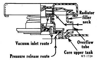
The cap (Fig. 1) has a spring-loaded valve, the seat of
which is below the overflow pipe in the filler neck. This
prevents the escape of air or liquid while the cap is in
position. When the cooling system pressure reaches a
predetermined point, the cap valve opens and will
again close when the pressure drops below the
predetermined point.
When removing the pressure type cap from the
radiator, perform the operation in two steps. Loosen
the cap to its first notch to raise the valve from the
gasket and release the pressure through the overflow
pipe. In the first stage position of the cap it should be
possible to depress the cap approximately 3 mm
(1/8"). The depression can be adjusted
Fig. 1 Radiator Cap (Pressure Type)
by bending the prongs on the cap. Care should be
taken when bending the prongs to ensure the cap is
not too loose as this would prevent proper sealing.
Then slowly continue to turn cap counterclockwise until
you can remove it.
NOTE: When removing the cap, loosen it slowly and then pause
to allow the pressure to bleed. This will avoid possible burning
by hot water or steam.
6.
Reservoir System-(if so equipped). The reservoir
installation consists of a simple, plastic reservoir
mounted near the radiator cap, coolant lines and a
special radiator cap (Fig. 2). Once the radiator cap is
installed, it should not be removed except when the
cooling system is cold and for refilling after the entire
system is drained. With this system, coolant make-up
originates from the reservoir. Coolant overflowing
from the radiator enters the reservoir to be conserved
until drawn back into the cooling system (engine and
radiator) when it cools down. The reservoir installation
provides a means of removing air from the cooling
system and keeping the coolant level at a maximum fill
condition.
The following illustrations explain the operation of this
system under conditions that exist in the cooling system.
Fig. 3: Initial condition of the system. The reservoir is
filled to the "FULL" line. The radiator has been filled to the filler
neck. Engine has started and as system begins to warm up,
expanding air in the system is expelled through the open
vacuum valve and out the radiator overflow tube into the
reservoir where it escapes at the reservoir overflow outlet.
CTS-2019P Page 5
PRINTED IN UNITED STATES OF AMERICA
|