|
| |
TRUCK SERVICE MANUAL
TM 5-4210-230-14&P-1
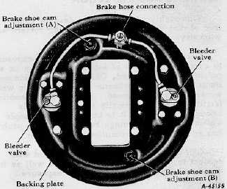
Fig. 2 External View
DESCRIPTION
These self-centering type brakes have two single end
wheel cylinders, each operating a forward acting shoe
providing directional braking response. The closed end of the
wheel cylinder has a slotted ramp which is the self-centering
sliding anchor for the opposite shoe. The two wheel cylinder
pistons apply equal amounts of hydraulic force to each shoe
toe.
Shoes are adjustable manually by means of two hex head
friction spring locked studs, exposed on the backing plate
(Fig. 2). Each stud rotates an adjuster cam located under a
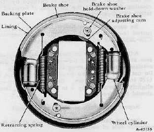
brake shoe table. Shoe hold-downs consist of two plain
washers, multi-rattle wave washer between and a C-clip fitted
over the extended shank of the cam stud. Two retracting
springs are hooked between the shoes and have their longer
shanks connected to the anchor end of the shoes.
Upon brake application, the wheel cylinder pistons
transmit pressure to the toes of the shoes, forcing the shoe
linings into contact with the brake drum. If the vehicle is
moving forward, the drag of the drum against the shoe lining
produces "self-energization" which tends to help rotate the
shoes outwardly about their anchor points. This action
multiplies the forces exerted against the drum and produces
additional braking effect. Both shoes are forward acting
(primary shoes), self-energizing in the forward direction of
drum rotation.
If the vehicle is moving backward, the drag of the drum
on the linings is in the opposite direction and produces "de-
energization" which tends to move the shoe heels away from
their anchor blocks. Piston forces at the shoe toes are large
Fig. 3 Internal View
enough to overcome this action, but the shoes tend to rotate
inwardly about their anchor points and attempt to leave the
drum. Both shoes are reverse acting since neither is self-
energized in the reverse direction of drum rotation.
Cylinder anchor block sides are aligned on the axle
radius. As the shoes roll upon their anchor blocks to contact
the drum, the heels may also slide radially upon the anchor
block surface. The shoes thus automatically "selfcenter" in
relation to the drum.
The self-energization factor causes this brake to be
approximately three times as effective during forward
operation as it is during reverse operation; therefore its use is
generally confined to the front axle of vehicles in conjunction
with a rear axle brake of a type providing effective stopping
ability in reverse as well as forward motion.
LINING CLEARANCE ADJUSTMENT
Lining to drum clearance adjustment is required when
shoes are relined and, on occasion, to compensate for normal
lining wear. Clearance should be sufficient to avoid "brake
drag" and yet close to afford a good "pedal reserve".
Manually
operated
and
vacuum-hydraulic
actuated
brakes require adjustment (or relining) when pedal reserve
approximates 2"; that is, when the brake pedal drops to within
2" of floor board on hard application.
Adjustment is made with the vehicle resting
CTS-2078T - Page 3
PRINTED IN UNITED STATES OF AMERICA
|