|
| |
TRUCK SERVICE MANUAL
TM 5-4210-230-14&P-1
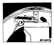
Fig. 7
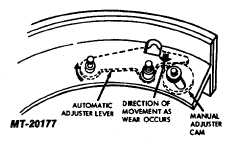
When installing shoe on hold-down, free end
of adjuster lever should bear against manual
adjuster cam which should be fully backed off
to position shown in Fig. 8.
Fig. 8
9.
Install flat washers and hold-down "C" washers.
10.
Install brake shoe return springs.
11.
Remove wheel cylinder clamps.
12.
Back off manual adjustment cams.
13.
Center each shoe before installing drum by sliding
shoe up or down in its anchor slot until the leading
and trailing edges of linings are equal distances from
the rolled edge of brake backing plate. 14. Repack
wheel bearings (refer to LUBRICATION, CTS-2412).
15.
Reinstall wheel bearings, new seals and install hub
and drum assembly. Adjust wheel bearings. Refer
to WHEELS, RIMS and TIRES Section (CTS-2032)
for proper instructions pertaining to repacking
bearings and bearing adjustment.
16.
Adjust brakes by performing the initial manual
adjustment,
referring
to
LINING
CLEARANCE
ADJUSTMENT procedure.
17.
If wheel cylinders were rebuilt or replaced the brakes
will
require
bleeding.
Refer
to
BRAKES
HYDRAULIC, General (CTS-2055 for single system
or CTS-2470 for split system).
18.
Remove floor stands from under vehicle.
LINING CLEARANCE ADJUSTMENT
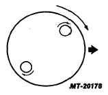
Adjust Each Shoe, in Turn: With drum installed, rotate
adjuster cam stud and drum in forward direction of drum
rotation until a light drag is noticeable (Fig. 9). Do not apply
excessive force on the stud -13.6 Nm (120 inch pounds)
maximum. Back off adjuster stud (6 to 12 degrees) until drum
turns freely. After the manual adjustment is performed, the
automatic adjusters will now maintain normal facing-to-drum
clearance.
Fig. 9
CTS-2491T Page 5
PRINTED IN UNITED STATES OF AMERICA
|