|
| |
TRUCK SERVICE MANUAL
TM 5-4210-230-14&P-1
IMPORTANT
Contact plug must be replaced when new
lining is installed. Do not use oversize
thickness lining, even though drums are
rebored.
Do
not
lubricate
adjuster
mechanism.
If new lining has no contact plug hole, cut a 19.05 mm
(3/4") hole and deburr the edges. Locate this hole by making a
proper template of the shoe table.
WHEEL CYLINDERS
Inspect wheel cylinders for signs of fluid leakage or
deteriorated rubber dust boots. If brake fluid is leaking out of
wheel cylinders, replace or recondition wheel cylinders.
Some brake groups have wheel cylinder piston stops and
the wheel cylinder must be removed for reconditioning.
RETRACTING
SPRINGS
AND
SELF-ADJUSTING
MECHANISM COMPONENTS
Inspect retracting spring for distortion such as nicks,
twisted shanks or spread of coils. Damaged spring must be
replaced.
Inspect
self-adjusting
mechanism
components
for
damage or wear, any piece of which the condition is
considered questionable must be replaced.
REINSTALL BRAKE SHOES
1.
Position wedge guide in shoe web hole on side away
from brake backing plate, with serrations facing away
from shoe table. Lay wedge with serrations matched
against guide and slot aligned over the lever pivot pin
hole shoe web (Fig. 4).
Fig. 4
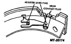
2.
Insert contact plug into the web recess and guide it
into the shoe table with plug shank over the wedge
guide and wedge. Insert adjuster lever pins through
shoe from the
opposite side and mate the actuating (center) pin with the plug
shank hole (Fig. 5).
3.
Assemble wedge washer over shoulder of pivot pin.
4.
Slide U-hook of tension spring on pin over contact
plug shank.
Fig. 5
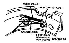
5.
Hook one end of wedge (coil) spring on the U-hook,
then install coil of torsion spring over the pivot pin
and pull free spring hook over the edge of the shoe
web. Hook free end of wedge spring over finger on
wedge (Fig. 6).
Fig. 6
6.
Press lightly upon contact plug to allow wedge to
move and fully retract the wedge against the lever
pivot pin. In this position, the plug should be even
with lining surface + 0.00 to-0.512 mm (+ 0.00 to-
0.006 inch If plug is high, clamp shoe in a vise so
that the jaws of the vice bear against the adjuster
lever (Fig. 7) and dress down the plug with a file.
Take care not to create a flat spot on the lining. An
alternate method is to dress the plug when the shoes
are ground to a true radius; however, lever must be
blocked in its extended position.
7.
Make sure that brake backing plate, wheel cylinder
anchor bolts and cylinder mounting screws are
tightened securely.
8.
Install shoes on hold-downs, locating each retracting
spring so that its long shank is hooked at the anchor
end of the shoe.
CTS-2491T Page 4
PRINTED IN UNITED STATES OF AMERICA
|