|
| |
TRUCK SERVICE MANUAL
TM 5-4210-230-14&P-1
BODIES AND CABS
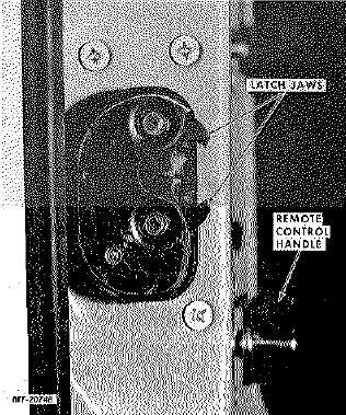
Fig. 20 Door Latch Assembly
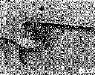
Fig. 21 Removing Remote Control Assembly
Install (Refer to Fig. 19 for Component Details)
1.
Position latch assembly to inside of door. Latch jaws
must be closed and the three relay control rods
should be preassembled to latch.
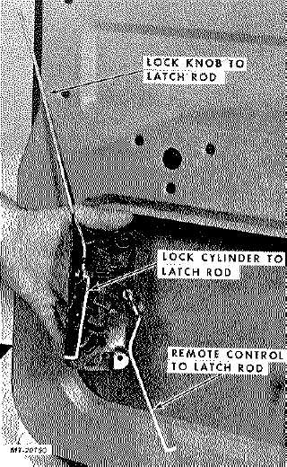
Fig. 22 Removing Latch Assembly
2.
Pilot threaded end of upper lock knob rod through
lock knob hole in window frame while positioning
latch. Install lock knob.
3.
Secure latch assembly in door with five socket head
screws.
4.
Position remote control assembly in door and secure
with three socket head screws.
5.
Connect the two remaining relay control rods to
remote control assembly and to lock cylinder lever.
Secure rods with rod end clips.
6.
Operate latch assembly to assure correct assembly.
CTS-2714 Page 15
PRINTED IN UNITED STATES OF AMERICA
|