|
| |
TRUCK SERVICE MANUAL
TM 5-4210-230-14&P-1
BODIES AND CABS
1.
Raise hood.
2.
Connect SE-2443 Service Station to air conditioning
system service ports as follows:
a.
Close manifold suction and discharge gauge
valves (turn fully clockwise).
b.
Remove cap from compressor suction service
port. Connect manifold suction gauge hose to
compressor suction service port.
c.
Remove cap or engine fan drive override
switch
(if
equipped)
from
compressor
discharge service port. Connect manifold
discharge
gauge
hose
to
compressor
discharge service port.
d.
Route the service hose from the center
manifold fitting into the shop exhaust removal
system or out of doors.
3.
Open the manifold gauge valves a slight amount and
allow refrigerant to discharge SLOWLY.
Do not allow refrigerant vapor to discharge too
rapidly as it will carry out the compressor oil as well.
When refrigerant has been discharged, both manifold
gauges will read zero.
4.
After refrigerant has been removed, air conditioning
system components can be removed for service.
CHECKING COMPRESSOR OIL LEVEL
The compressor is designed to provide a pressurized
oiling system where required, without the use of a mechanical
pump. As long as a refrigerant flow is maintained, a certain
amount of oil will circulate with the refrigerant through the
system. When the compressor is operating, there is a
pressure difference between the top of the cylinder and the
crankcase. This pressure difference causes some oil to be
forced down the cylinder wall, thus lubricating some of the
compressor parts.
Since some of the oil from the compressor pump is
picked up and circulated through the system with the
refrigerant, it is very important that the compressor oil level be
checked whenever the system is opened for service.
To check compressor oil level, proceed as follows:
1.
Discharge
refrigerant
from
system.
(See
"Discharging the Air Conditioning System".)
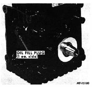
2.
Remove oil fill plug from side of compressor (Fig.
36).
In some cases it may be necessary to remove
compressor from engine to gain access to oil fill
plug.
Fig. 36 Compressor Oil Fill Plug
3.
Insert dipstick through oil fill hole until it bottoms in
compressor crankcase.
It may be necessary to rotate compressor crankshaft
slightly to permit entrance of dipstick. Be certain that
dipstick is bottomed in crankcase.
Dipstick can be made locally from a 3.175 mm (1/8")
diameter steel rod as shown in Fig. 37, or is
available under service tool number SE-2392-3.
Fig. 37 Dimensions for Making Oil Level Dipstick
CTS-2731 Page 22
PRINTED IN UNITED STATES OF AM ERICA
|