|
| |
TRUCK SERVICE MANUAL
TM 5-4210-230-14&P-1
BODIES AND CABS
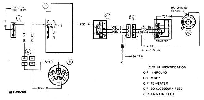
Wiring Circuit Diagrams
Heater and air conditioning system wiring circuit
diagrams are illustrated in Figs. 16 and 17.
For complete vehicle wiring circuit diagrams, refer to
ELECTRICAL, Section CTS-2719 of the Truck Service
Manual.
COMPONENT IDENTIFICATION CODE
(For Figures 16 and 17)
Key
Component
Key
Component
AA
Heater and A/C Connector
J
Bulkhead Connector
AB
A/C Relays
L
Fuse Block
AC
Blower Motor
Q
Instrument Panel Connector
AD
Thermostatic Temperature Control Switch
R
Key Switch
AE
Blower Switch
V
Feed Stud
Fig. 16 Heater Wiring Diagram
CTS-2731 Page 10
PRINTED IN UNITED STATES OF AMERICA
|

