|
| |
TRUCK SERVICE MANUAL
TM 5-4210-230-14&P-1
BODIES AND CABS
Insufficient evaporation could result in "slugging” -
drawing of liquid refrigerant into the compressor. Also an
insufficient flow of refrigerant does not provide adequate
compressor lubrication.
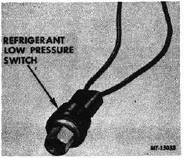
If evaporator outlet pressure drops to approximately
34 kPa (5 psi) the low pressure switch closes, throwing the
low pressure switch relay, to break the feed circuit to the
magnetic clutch and disengage the clutch. (See wiring circuit
diagram, Fig. 17.)
Fig. 13 Low Pressure Switch
Fan Drive Override Switch
Vehicles equipped with an engine cooling fan clutch
have a fan drive override switch located in the refrigerant
compressor discharge service port.
If
compressor
discharge
pressure
exceeds
approximately 2070 kPa (300 psi), this switch engages the
engine fan drive clutch to provide maximum air flow through
the condenser.
The fan drive override switch is similar in appearance
to the low pressure switch illustrated in Fig. 13.
Solenoid Control Valves
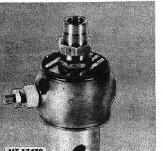
Two identical solenoid operated control valves (Fig.
14) may be used in conjunction with the air conditioning
system to assure that there is sufficient air flowing through the
condenser to prevent excessive refrigerant compressor head
(discharge) pressure.
The
shutter
control
valve,
activated
by
the
thermostatic temperature control switch, opens the radiator
shutter and keeps it open (overriding the engine's shutter
control) while the air conditioning system is "ON".
Fig. 14 Solenoid Valve
On engines equipped with an engine cooling fan
clutch, the fan drive solenoid valve, responding to activation
by the fan drive override switch, engages the fan clutch
whenever
compressor
discharge
pressure
becomes
excessive.
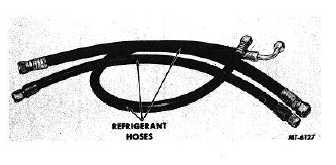
Refrigerant Hoses
Hoses and tubing are used to carry the refrigerant
from the compressor to the various components of the air
conditioning system and back to the compressor. The hoses
(Fig. 15) must withstand certain temperatures and pressures.
Therefore it is very important that only hoses of the correct
sizes and types be used in the air conditioning system.
Fig. 15 Refrigerant Hoses
Refrigerant
The refrigerant is the substance which absorbs and
removes the heat from the cab. It must be a substance that
can be easily converted from a liquid to a vapor and back to a
liquid at reasonable temperatures. In other words, it must
vaporize at normal ambient temperatures so that it can
absorb the heat while passing through the evaporator.
The type of refrigerant used in IH air conditioning
systems is R-12.
CTS-2731 Page 9
PRINTED IN UNITED STATES OF AMERICA
|


