|
| |
TRUCK SERVICE MANUAL
TM 5-4210-230-14&P-1
the inside wheel is driven at ring gear speed while the
outside wheel is driven by the ground faster than ring
gear speed. When the rearward turn is nearing
completion and the vehicle is slowing down because of
application of the brakes, the outside wheel is driven by
the ground at ring gear speed, as its driven clutch
member is fully engaged and acts to "brake" against the
engine torque. The inside wheel is driven by the ground
through the smaller arc of travel, and since its driven
clutch member is disengaged, it will rotate slower than
ring gear speed.
Fig. 42 shows the operation of the differential
when a right-hand turn in a rearward direction is being
negotiated.
DIFFERENTIAL REMOVAL
The procedure for removing the differential is
the same as used for a conventional differential.
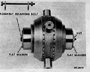
IMPORTANT PRECAUTION: Before disassembling the
differential case, insert a bolt through the center of the
NoSPIN unit (axle shaft openings) with a flat washer on
each end against the side members, Fig. 43.
Thread a nut on the bolt against the flat washer
finger tight. This will prevent possible injury caused by
the unit flying apart due to the spring pressure within
itself during disassembly of the differential case.
Fig. 43 Inserting Assembly Retaining Bolt
DISASSEMBLY
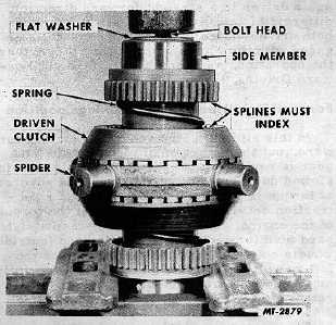
Remove the bolts from the differential case and
lift out the NoSPIN unit. Mount unit in a small press,
Fig. 44.
Apply enough pressure on the head of the bolt
to release the spring pressure against the nut. Remove
the nut and flat washer by reaching
underneath the press. Slowly release the press and
allow the unit to disassemble itself until the spring
pressure is fully released.
Remove unit from press.
Fig. 44 Release of Spring Pressure
Remove
side
members,
springs,
spring
retainers and driven clutch members. The center cam
may be removed from the spider by expanding the snap
ring with small screwdrivers or wedges.
NOTE:
Be
careful
when
removing
and
reinstalling center cam snap ring to avoid possible
injury.
CLEANING, INSPECTION AND REPAIR
Wash all parts thoroughly with a cleaning
solvent. Inspect all mating surfaces and teeth for
possible wear or damage. Replace all worn or damaged
parts before reassembly.
REASSEMBLY
Reassembly is essentially the reverse of
disassembly. Lubricate all parts with SAE-30 oil during
reassembly. Place side member upright and install
spring on same. Place spring retainer on spring with
flange end toward side member. Install driven clutch
member on spring retainer. Place spider on driven
clutch member, indexing teeth of same. Install other
driven clutch member, spring retainer, spring and side
member on spider.
Insert a bolt through the center of the NoSPIN
unit with a flat washer against side
CTS-2095S - Chapter II - Page 6
PRINTED IN UNITED STATES OF AMERICA
|


