|
| |
TRUCK SERVICE MANUAL
TM 5-4210-230-14&P-1
punch to press out remaining portion of the rivet.
NOTE
Never use chisel to cut off rivet heads or
damage to differential case might result.
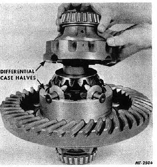
Fig. 13 Separating Differential Case Halves
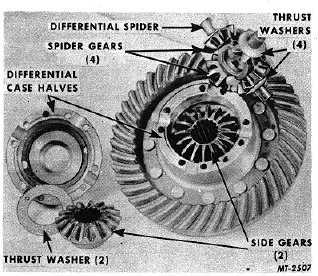
Fig. 14 Component Parts of Differential Case
5.
When reinstalling ring gear, it is suggested that
Riveting Fixture SE-2222 be used. This special tool
is designed for use with either hydraulic or
mechanical press equipment. Rivet pressures for
ring gear installation should be in accordance with
those given in the following chart.
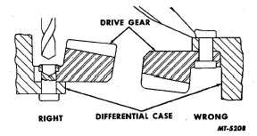
Fig. 15 Drive Gear Rivet Removal
Rivet Size
Pressure Per Rivet
Inch mm
U.S. Tons/Metric Tons
7/16
11.1125
18-20
16.3-18.1
1/2
12.7
20-25
18.1-22.7
5/8
15.8750
45-50
40.8-45.3
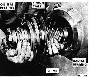
Remove Pinion and Cage from Differential Housing
There are two methods for removing the pinion and
cage assembly and the method to be used will depend on
whether puller screw holes have been provided in the pinion
cage flange or not. When no puller screw holes are provided,
removal is as follows:
1.
Remove pinion cage capscrews which hold the cage
to the differential carrier.
2.
Remove pinion and cage assembly from the
differential carrier, Fig. 16.
Fig. 16 Removing Pinion and Cage Assembly
CTS-2095S-CHAPTER I-Page 7
PRINTED IN UNITED STATES OF AMERICA
|