|
| |
TM 5-4210-230-14&P-1
TRUCK SERVICE MANUAL
4.
Check trunnion bearing adjustment by placing a torque
wrench on trunnion cap or steering arm retaining nut
and swinging trunnion housing. Torque should be 11
to 20 Newton Meters (8 to 15 ft.lbs.). To increase
torque, remove shims, to decrease torque, add shims.
See Fig. 20.
5.
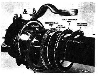
Install gasket, flange, steering ball felt, seal with spring,
split retainer ring and' retaining ring halves on rear of
trunnion housing. See Fig. 21 for correct order or
component installation.
Fig. 21 Trunnion Housing Seals and Retainers
Install
retaining
half
(halves)
lockwashers
and
mounting bolts. Torque mounting bolts ,6 14 to 20
Newton Meters (10 to 15 ft lbs.).
6.
Install axle shaft and universal joint assembly in axle
housing indexing splined end of axle shaft with side
gear of center unit (Fig. 22). When installing axle shaft
and universal joint assembly care should be taken not
to damage axle shaft oil seal.
7.
Slide spindle over universal joint shaft and on to
trunnion housing studs.
8.
Fill axle housing end with lubricant through grease zerk
located behind trunnion housing on top center of
exposed portion of steering ball.
9.
Axle end assembly is now complete. Spindle is retained
to trunnion housing by brake group retaining nuts upon
brake group reassembly.
Fig. 22 Axle Shaft and Universal Joint Assembly
CTS-2658S Page 19
PRINTED IN UNITED STATES OF AMERICA
|