|
| |
TRUCK SERVICE MANUAL
TM 5-4210-230-14&P-1
WHEELS, RIMS, TIRES
CHAPTER I
WHEELS
GENERAL
The information presented herein covers factory installed wheels and hubs for medium and heavy duty vehicles. Many types
of wheels are available and they vary in size, types (disc or cast) and materials (steel or aluminum). Fundamentally, they are the
same in that all wheels (or hubs for disc wheels) are mounted to the axles on tapered roller bearings.
SAFETY PRECAUTIONS
Always deflate tires completely before removing locks or side rings.
Always inspect and clean all parts before assembly.
Always inflate tires in safety cage.
Always use a "clip-on" air chuck with remote valve to inflate tires.
Never mix parts of different types or size.
Never use cracked, bent or badly rusted parts.
Never reinflate flat tire on vehicle--use the spare.
Never add air until certain each side or lock ring is fully seated.
WHEEL BEARING ADJUSTMENT
Satisfactory wheel operation and long bearing life
depends on correct wheel bearing installation, lubrication and
adjustment. The following will help you perform these
required services for wheels and hubs.
FRONT WHEEL BEARINGS
Wheels or hubs, bearing cups, nuts, locks, hub caps,
shafts and spindles are to be free from any foreign matter.
Bearing cones must be properly packed with specified
lubricant if wheels are grease packed (see LUBRICATION,
Section
If wheel bearings are oil lubricated dip bearing cones in
lubricant to provide proper starting lubrication. Outer surface
of bearing cone and matching surface of cup may be coated
with lubricant to promote cone-to-cup adhesion and facilitate
assembly.
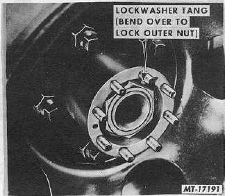
After wheel (or hub) and bearings are assembled in place on
the spindle, tighten the wheel bearing adjusting nut to 69 N•m
(50 ft lbs) while rotating the wheel. Then back off the nut 1/4
turn. If the lock or cotter key can be installed at this position,
do so; if not,
tighten to the nearest locking position and insert new key or
lock. Bent type lockwasher is to have one tab bent over the
adjusting nut. For axles that have double nut type lock,
tighten jam nut to 136-203 N•m (100 -150 ft lbs) and bend one
tab of the lockwasher over the jam nut (Fig. 1). These
procedures are intended to result in zero to .25mm (.010") end
play with no preload.
Fig. 1
CTS-2032N Page 1
PRINTED IN UNITED STATES OF AMERICA
|