|
| |
TRUCK SERVICE MANUAL
TM 5-4210-230-14&P-1
TRANSMISSION
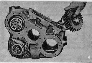
Fig. 15.
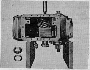
Fig. 16.
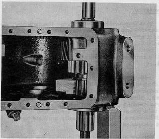
Fig. 17.
26. Remove speedometer drive gear and spacer.
27. Block gear with a piece of wood and press rear output
shaft and front bearing out of the case as shown (Fig.
16). The gear and rear bearing can be lifted out through
cover hole.
28. Remove input shaft front bearing cover. Wire shim pack
together for reassembly.
29. Using a block of wood between sliding gear and case,
press out input shaft and front bearing (Fig. 17). Do not
pound on shaft if gear becomes bound.
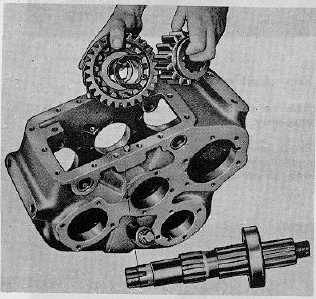
30. Lift out sliding gear, drive gear and Spacer (Fig. 18).
Remove front bearing from shaft.
Fig. 18
Disassembly of Power-Take-Off
1.
Remove capscrews and lockwashers; /lift off cover
and gasket
2.
Take out detent spring and ball.
3.
Cut wire and loosen shift fork set screw.
4.
Tap shift shaft out through rear of housing
(expansion plug will fall out).
5.
Remove shift shaft and shift fork (Fig. 19).
CTS-2048Q Page 7
PRINTED IN UNITED STATES OF AMERICA
|